Hydraulic elastic chuck and clamping method thereof

An elastic collet and hydraulic technology, which is applied in the field of mechanical processing, can solve the problem of not being able to determine that the starting processing position of the workpiece is the same, affecting the processing accuracy and production efficiency of the product, and poor self-centering accuracy of the mechanical three-jaw chuck. problems, to achieve the effect of simple structure, improved machining accuracy and production efficiency, and flexible operation

Pending Publication Date: 2018-11-13
梅木精密工业(珠海)有限公司
View PDF1 Cites 3 Cited by
  • Summary
  • Abstract
  • Description
  • Claims
  • Application Information

AI Technical Summary

Problems solved by technology

[0002] At present, there are generally two types of clamping methods for machining workpieces in machine tools: the first is mechanical three-jaw chuck clamping, and the second is to clamp the workpiece by hydraulic pressure to force the elastic deformation of the thin-walled sleeve, that is, the hydraulic chuck; The self-centering accuracy of the mechanical three-jaw chuck is poor, the operation is inflexible, and the labor intensity is high, which greatly affects the processing accuracy and production efficiency of the product; the structure of the second hydraulic chuck (such as the Chinese utility model patent "a hydraulic chuck head tooling", authorized announcement number: CN 201659445U), the inner core and the clamping sleeve are respectively provided with a connected oil ci

Method used


Image

  • Hydraulic elastic chuck and clamping method thereof
  • Hydraulic elastic chuck and clamping method thereof
  • Hydraulic elastic chuck and clamping method thereof

Examples


Embodiment 1

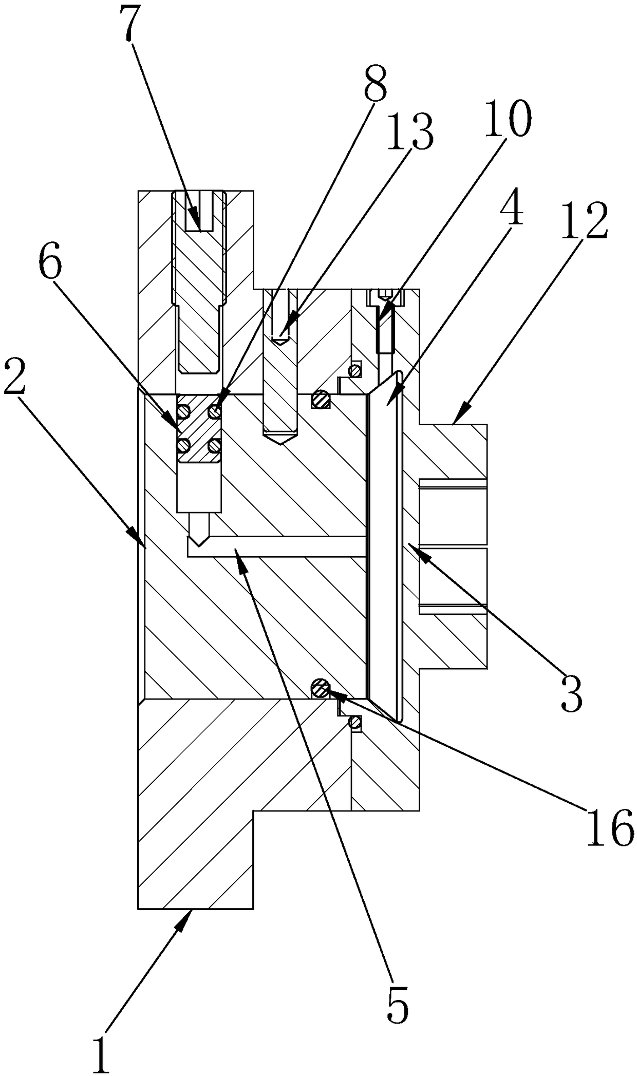
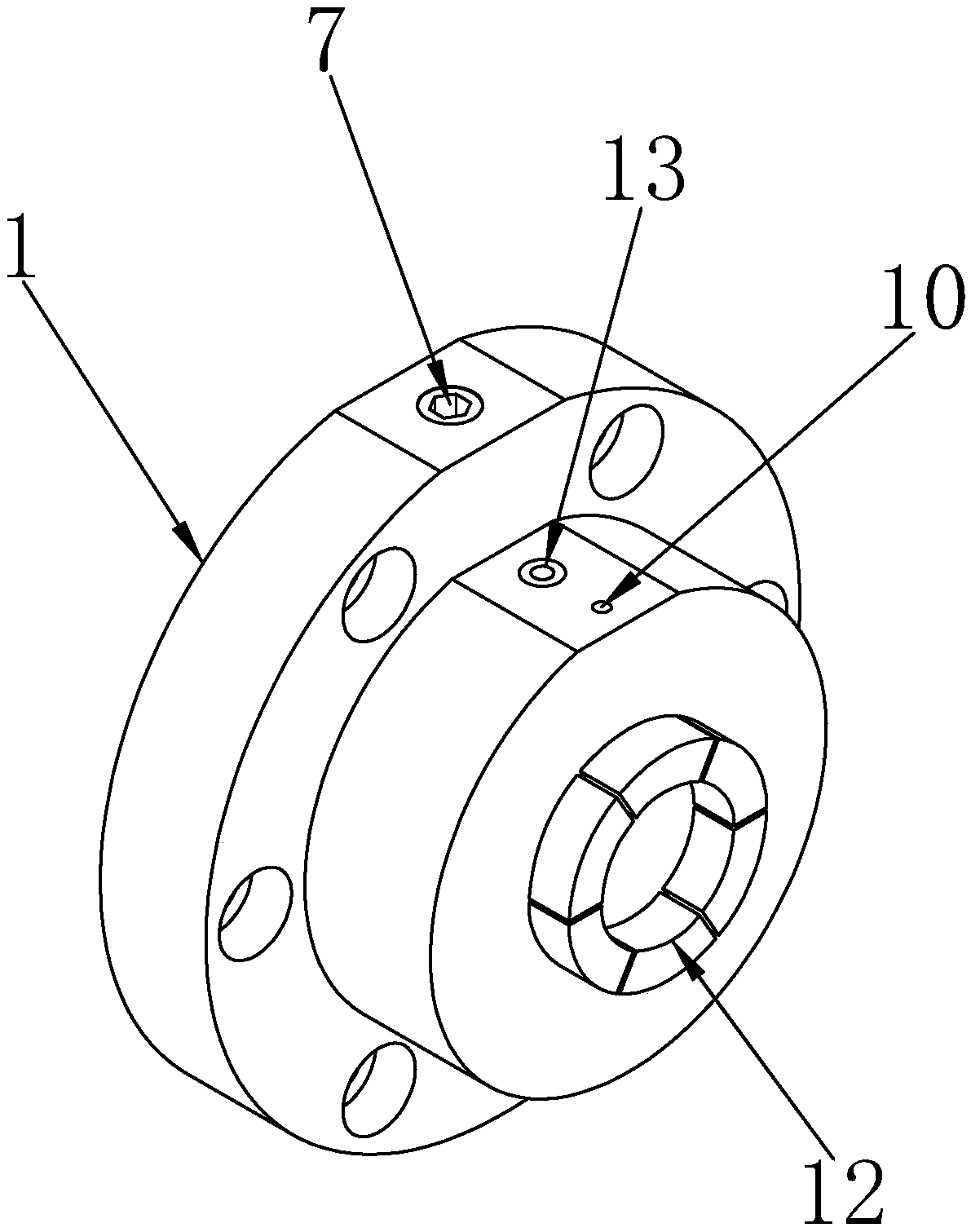
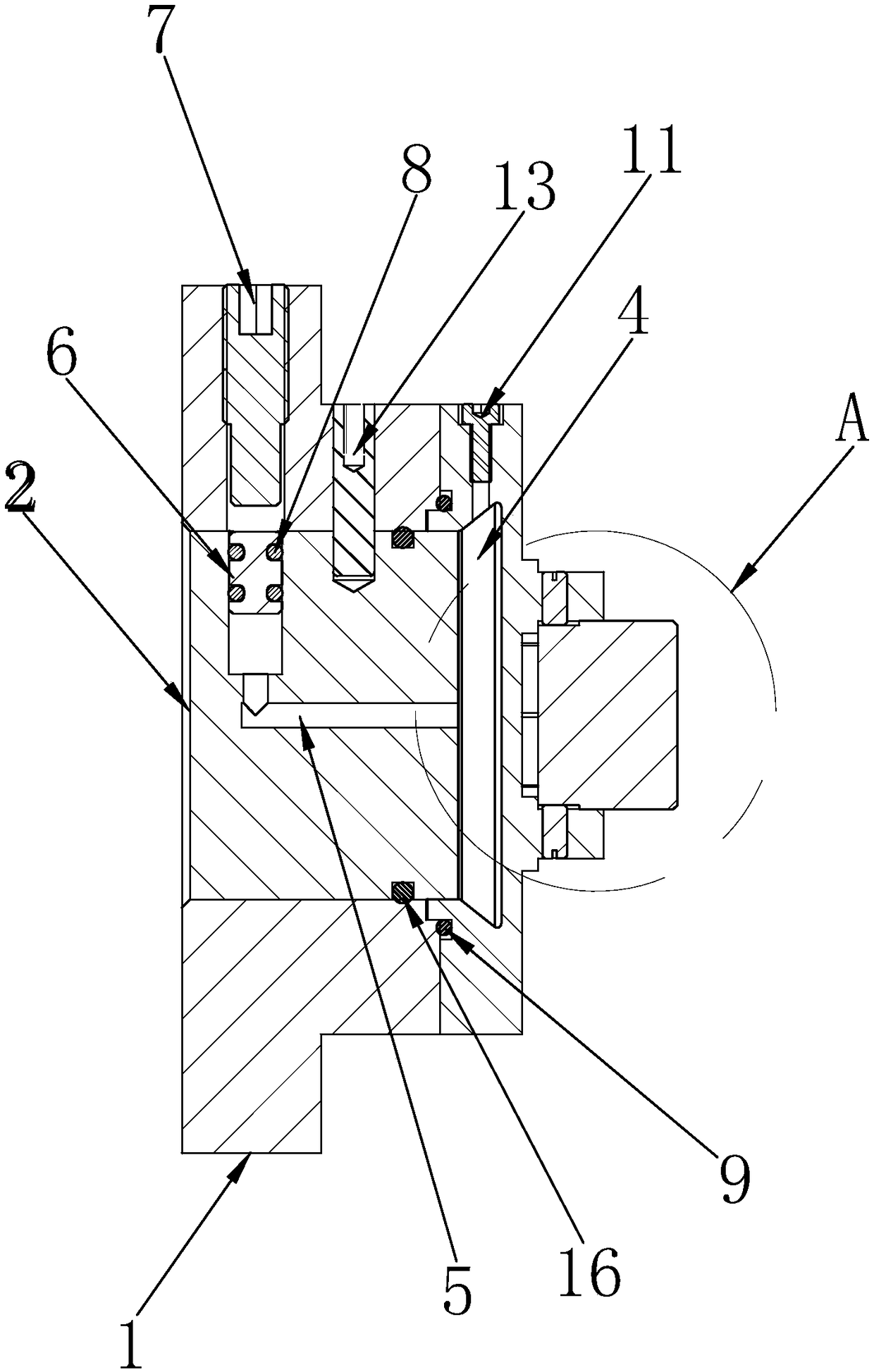
[0038] A hydraulic collet, such as figure 1 and figure 2 As shown, an overcoat 1 is included, and the front end of the overcoat 1 is provided with a chuck body. The rear end is provided with an inner cavity, and the inner cavity is sleeved with an inner core 2. In this embodiment, the chuck body includes a thin wall 3 and several claws 12 arranged at the front end of the thin wall 3 along the circumferential direction. In this embodiment, preferably Six claws 12 are used, and the six claws 12 form a ring along the circumference. The area between the front end of the inner core 2 and the rear end of the thin wall 3 forms an oil chamber 4, and an oil chamber 4 is provided between the inner core 2 and the inner chamber. The third sealing ring 16 ensures good sealing performance in the oil chamber through the third sealing ring 16. The inner core 2 is provided with an oil passage 5 communicating with the oil chamber 4, and the outlet of the oil passage 5 is provided with a movab...

Embodiment 2

[0044] Such as Figure 3 to Figure 5As shown, the difference between this embodiment and the first embodiment above is that a stepped structure 15 is provided on the inner side and / or outer side of the jaw 12, and when the workpiece is clamped, one end of the workpiece is tightened under the action of continuous external thrust. Paste the step structure 15 to ensure the positioning accuracy of the workpiece in the axial direction. The same batch of workpieces can use the step structure 15 to ensure that the same batch of workpieces obtains the same machining accuracy and improve the machining accuracy of the workpiece; The inner side of the jaw 12 is provided with a stepped structure 15, which can process shaft parts, and the outer side of the jaw 12 is provided with a stepped structure 15, which can process hole parts, and the inner and outer sides of the jaw 12 are provided with a stepped structure 15, The purpose is to make the chuck body adaptable to two kinds of workpiece...

Embodiment 3

[0049] A clamping method realized by the above-mentioned embodiment 1 or embodiment 2 of the hydraulic elastic chuck. In this embodiment, the workpiece is a shaft part, which includes the following steps:

[0050] A. Fix the hydraulic elastic chuck on the machine tool spindle, which can be fixed on the machine tool spindle by bolt connection;

[0051] B. By screwing and tightening the compression bolt 7, the sealing plunger 6 is pushed to move along the oil passage to pressurize the hydraulic oil, and the thin wall 3 is slightly deformed and bulged outward by the pressing action of the hydraulic oil, thereby driving the jaws 12 open;

[0052] C. Load the workpiece into the jaw 12;

[0053] D. Reversely screw the compression bolt 7 to eliminate the pressure of the sealing plunger 6 on the hydraulic oil, so that the outwardly bulging thin wall 3 returns to its original shape, and the jaws 12 shrink, thereby clamping the workpiece and ensuring the radial positioning of the workp...


PUM


Abstract

The invention relates to the technical field of machining and particularly relates to a hydraulic elastic chuck and a clamping method thereof. By pushing a sealing plunger to pressurize hydraulic fluid, a thin wall deforms and expands outwards, claws at the front end of the thin wall are driven to stretch outwards, and the claws loosen workpieces or clamp the workpieces. The structure is simple, the production cost is low, and the operation is flexible. The clamping of the workpieces is convenient, the machining precision of the workpieces is improved, and the production efficiency is increased. According to the machining method of the hydraulic elastic chuck, after the hydraulic elastic chuck is fixedly arranged on a machine tool spindle, machining is carried out on the outer sides and/orinner sides of the claws, and a ring formed by a plurality of claws which get together is highly concentric with the machine tool spindle, so that the machining precision can be improved; and then, through locating structures on the claws, the to-be-machined workpieces are precisely located in axial, radial and rotating directions, so that when the same batch of workpieces are massively produced,the initial machining position points of all workpieces are ensured to be the same, and the machining precision during the mass production of the products is improved.

Description

technical field [0001] The invention relates to the technical field of mechanical processing, in particular to a hydraulic elastic collet and a clamping method thereof. Background technique [0002] At present, there are generally two types of clamping methods for machining workpieces in machine tools: the first is mechanical three-jaw chuck clamping, and the second is to clamp the workpiece by hydraulic pressure to force the elastic deformation of the thin-walled sleeve, that is, the hydraulic chuck; The self-centering accuracy of the mechanical three-jaw chuck is poor, the operation is inflexible, and the labor intensity is high, which greatly affects the processing accuracy and production efficiency of the product; the structure of the second hydraulic chuck (such as the Chinese utility model patent "a hydraulic chuck head tooling", authorized announcement number: CN 201659445U), the inner core and the clamping sleeve are respectively provided with a connected oil circuit...

Claims


Application Information

Patent Timeline
IPC IPC(8): B23B31/16
CPCB23B31/16287
Inventor 杨宏伟
Owner 梅木精密工业(珠海)有限公司
Why Eureka
Try Eureka