
Cantilever type rolling device suitable for rolling processing of thin-walled cylindrical workpieces

A thin-walled cylinder and cantilever-type technology, applied in the direction of metal rolling, etc., can solve the problems of high labor intensity, uneven force on the workpiece, low production efficiency, etc., and improve the processing quality of the workpiece, the production efficiency of the workpiece, and the accuracy of clamping High and reduce the effect of labor intensity

Active Publication Date: 2017-09-05
LIAONING TECHNICAL UNIVERSITY
View PDF10 Cites 4 Cited by
  • Summary
  • Abstract
  • Description
  • Claims
  • Application Information

AI Technical Summary

Problems solved by technology

[0002] At present, the roll forming of thin-walled cylindrical workpieces is mainly realized by traditional roller presses. Before the traditional roller presses perform roll forming of thin-walled cylindrical workpieces, the workpiece clamping operation usually needs to be completed manually, resulting in the clamping of the workpiece. The precision is not high, and during the roll forming process of the workpiece, the workpiece always needs to be supported by the workers manually, resulting in a high labor intensity for the workers and low production efficiency
[0003] Since the workpiece always bears a large force during the roll forming process, under manual support, if the support force is not enough, it is easy to cause uneven force on the workpiece, which will lead to deflection and misalignment of the workpiece, and will also cause damage to the workpiece. The personal safety of workers brings certain hidden dangers
In addition, due to the large vibration of the traditional roller press during operation, this directly increases the difficulty of manual support, and ultimately makes it difficult to guarantee the processing quality of the workpiece

Method used


Image

  • Cantilever type rolling device suitable for rolling processing of thin-walled cylindrical workpieces
  • Cantilever type rolling device suitable for rolling processing of thin-walled cylindrical workpieces
  • Cantilever type rolling device suitable for rolling processing of thin-walled cylindrical workpieces

Examples


Embodiment Construction

[0019] The present invention will be further described in detail below in conjunction with the accompanying drawings and specific embodiments.

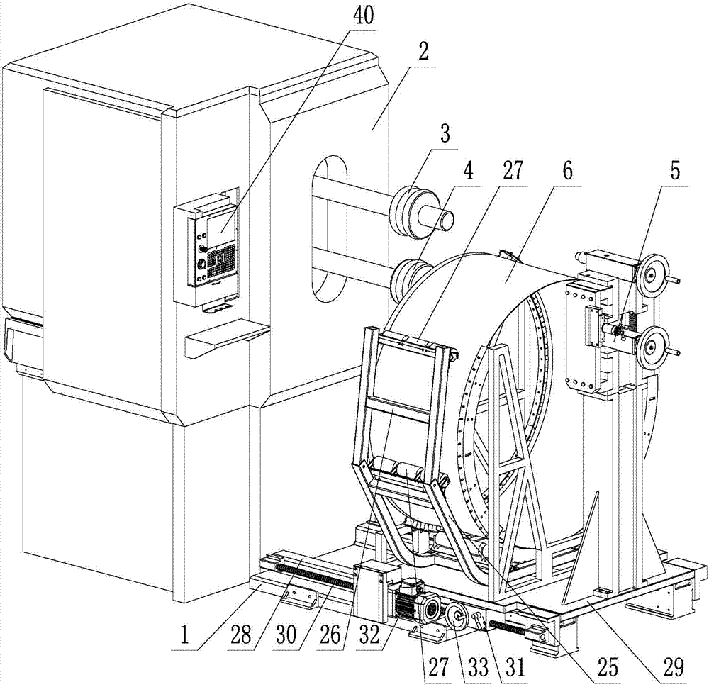
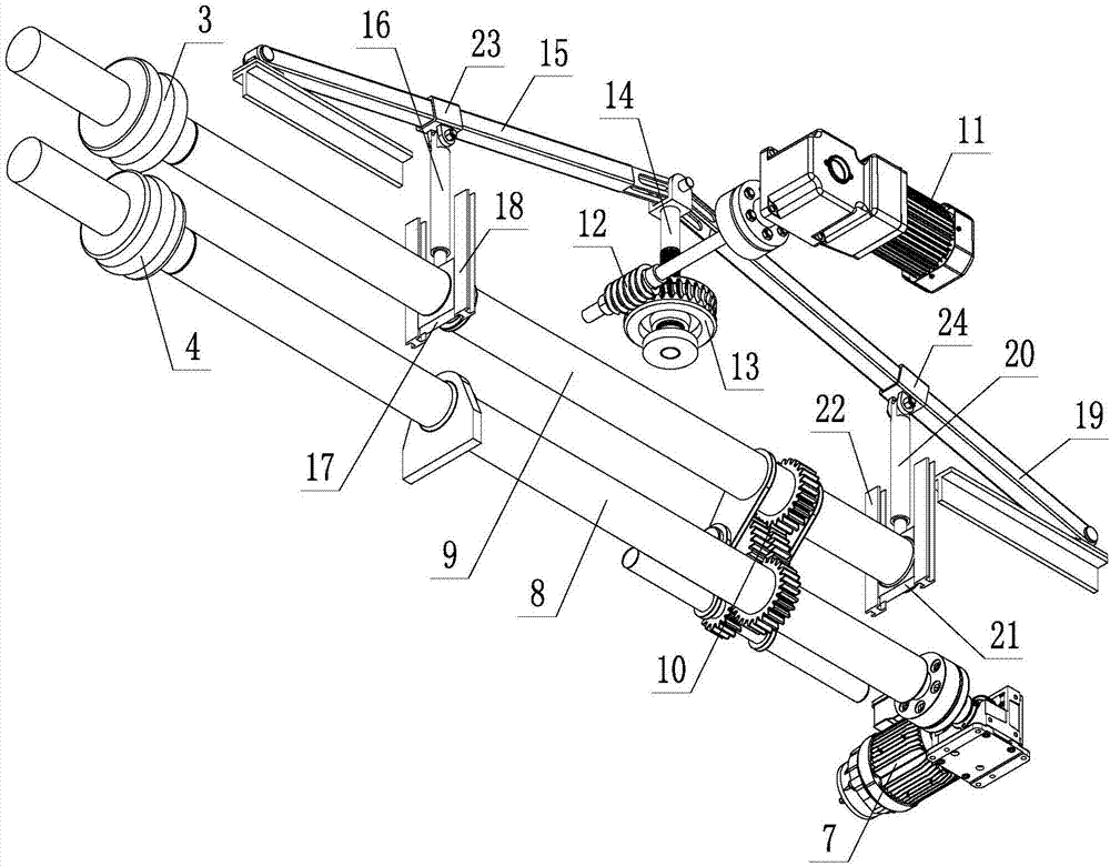
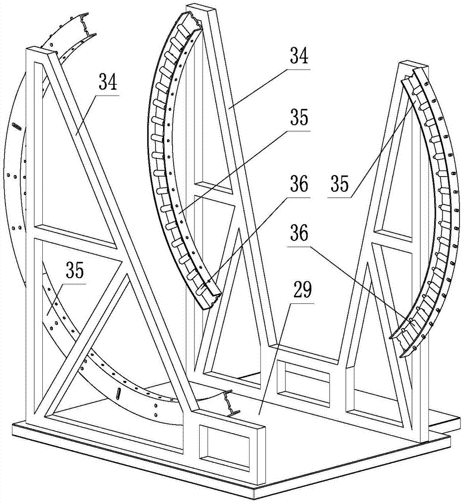
[0020] Such as Figure 1~4 As shown, a cantilever rolling device suitable for rolling processing of thin-walled cylindrical workpieces, including a base 1, a body 2, an upper work roll 3, a lower work roll 4, a work roll driving assembly, a pressing driving assembly, and a workpiece clamp The loading assembly and the work roll tighten the tailstock 5; the work roll drive assembly and the pressing drive assembly are located in the fuselage 2, and the upper work roll 3 and the lower work roll 4 are installed on the fuselage 2 through the work roll drive assembly , the depressing driving assembly is used to drive the upper work roll 3 to perform the depressing action; the workpiece clamping assembly and the work roll tightening tailstock 5 are all installed on the base 1, and the workpiece clamping assembly is located between the fuselag...


PUM


Abstract

A cantilever type rolling device suitable for rolling processing of thin-walled cylindrical workpieces comprises a base, a machine body, an upper working roll, a lower working roll, a working roll driving assembly, a downward pressing driving assembly, a workpiece clamping assembly and a working roll tightening tailstock, wherein the working roll driving assembly and the downward pressing driving assembly are positioned in the machine body; the downward pressing driving assembly is used for driving the upper working roll to carry out downward pressing action; the workpiece clamping assembly and the working roll tightening tailstock are mounted on the base; the workpiece clamping assembly is positioned between the machine body and the working roll tightening tailstock; a workpiece is positioned in the workpiece clamping assembly; the working roll driving assembly comprises a working roll driving motor, a driving shaft and a driven shaft; the working roll driving motor is connected with the driving shaft; the driving shaft is connected with the driven shaft through an idle gear system; the driving shaft and the driven shaft synchronously and reversely rotate; the lower working roll is mounted on the driving shaft; the upper working roll is mounted on the driven shaft; a sliding table plate is arranged on the base; and the workpiece clamping assembly and the working roll tightening tailstock are positioned on the sliding table plate.

Description

technical field [0001] The invention belongs to the technical field of metal rolling, and in particular relates to a cantilever type rolling device suitable for rolling processing of thin-walled cylindrical workpieces. Background technique [0002] At present, the roll forming of thin-walled cylindrical workpieces is mainly realized by traditional roller presses. Before the traditional roller presses perform roll forming of thin-walled cylindrical workpieces, the workpiece clamping operation usually needs to be completed manually, resulting in the clamping of the workpiece. The precision is not high, and in the process of workpiece roll forming, the workpiece always needs to be supported by workers manually, resulting in high labor intensity and low production efficiency. [0003] Since the workpiece always bears a large force during the roll forming process, under manual support, if the support force is not enough, it is easy to cause uneven force on the workpiece, which wi...

Claims


Application Information

Patent Timeline
Patent Type & Authority Applications(China)
IPC IPC(8): B21H1/06
Inventor 卢进南谢苗孙方红单德兴刘治翔
Owner LIAONING TECHNICAL UNIVERSITY
Learn More