
Coating film jig and bearing tool

A fixture and tooling technology, which is applied in the field of optical lens coating fixtures and bearing tooling, can solve the problems of low vacuum evaporation efficiency of lenses, and achieve the effects of avoiding scratches, ensuring clamping stability, and high clamping accuracy

Pending Publication Date: 2019-03-01
ZHEJIANG SUNNY OPTICAL CO LTD
View PDF0 Cites 4 Cited by
  • Summary
  • Abstract
  • Description
  • Claims
  • Application Information

AI Technical Summary

Problems solved by technology

[0004] The purpose of the present invention is to provide a coating jig and bearing tooling to solve the problem of low vacuum evaporation efficiency of lenses

Method used

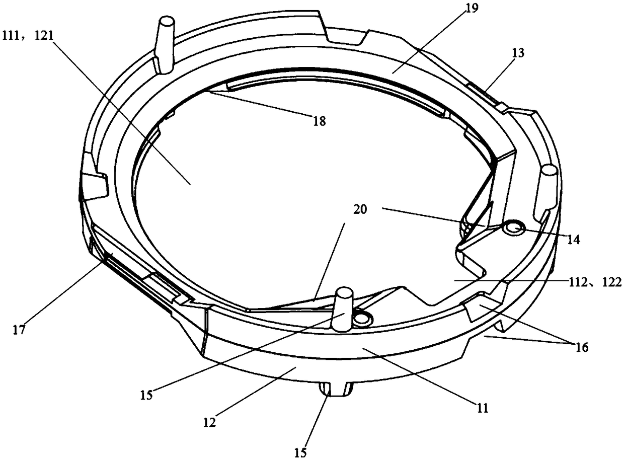
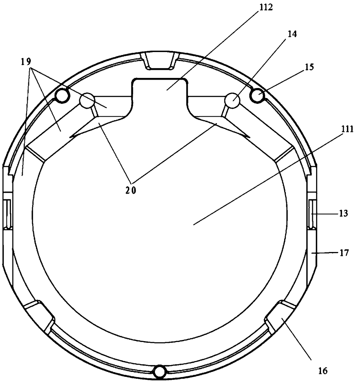
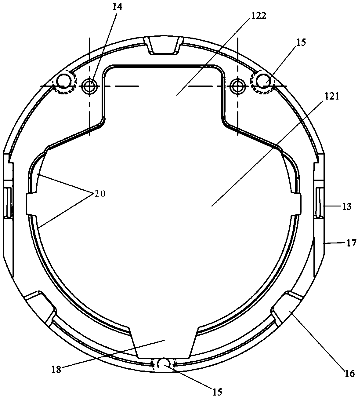

Image

  • Coating film jig and bearing tool
  • Coating film jig and bearing tool
  • Coating film jig and bearing tool

Examples


Embodiment Construction

[0034] In order to more clearly describe the embodiments of the present invention or the technical solutions in the prior art, the following will briefly introduce the drawings that are used in the embodiments. Apparently, the drawings in the following description are only some embodiments of the present invention, and those skilled in the art can also obtain other drawings according to these drawings without creative efforts.

[0035] When describing the embodiments of the present invention, the terms "vertical", "transverse", "upper", "lower", "front", "rear", "left", "right", "vertical", " The orientation or positional relationship expressed by "horizontal", "top", "bottom", "inner" and "outer" is based on the orientation or positional relationship shown in the relevant drawings, which are only for the convenience of describing the present invention and simplifying the description, and It is not to indicate or imply that the device or element referred to must have a particu...


PUM


Abstract

The invention relates to a coating film jig. The jig comprises a first clamping piece (11) and a second clamping piece (12) for clamping materials, and a connecting piece (13) for connecting the firstclamping piece (11) with the second clamping piece (12); the first clamping piece (11) is provided with a first through hole (111) and a first gap (112) communicated with the first through hole (111), and the second clamping piece (12) is provided with a second through hole (112) and a second gap (122) communicated with the second through hole (121); the first through hole (111) is communicated with the second through hole (112), and the first gap (112) is communicated with the second gap (122). According to the scheme, by adopting the combination mode of the first clamping piece and the second clamping piece, due to the clamping effect of the connecting piece, the materials can be rapidly clamped, production efficiency is improved, and the clamping precision is high.

Description

technical field [0001] The invention relates to a coating jig and a carrying tool, in particular to a coating jig and a carrying tool for an optical lens. Background technique [0002] With the continuous development of optical products, the scope of application of optical lenses is becoming wider and wider, followed by an increase in the production demand for optical lenses of various specifications and sizes. In order to reduce production costs, improve production efficiency, and meet the needs of mass production, various methods are used to manufacture optical lenses in the market. Among them, the vacuum evaporation coating method has become the most common method for preparing optical thin films in production due to the advantages of high purity and good quality of the prepared films, high film forming efficiency and fast speed. Therefore, how to produce a lens fixture and its tooling umbrella cover to meet the needs of rapid and efficient film formation by vacuum evapo...

Claims


Application Information

Patent Timeline
Patent Type & Authority Applications(China)
IPC IPC(8): C23C14/50C23C14/24
CPCC23C14/24C23C14/50
Inventor 余荣军蒯泽文朱亚蒙
Owner ZHEJIANG SUNNY OPTICAL CO LTD
Learn More