Rotary self-sharpening cutter mechanism

A technology of a rotary drive mechanism and a rotary transmission mechanism, which is applied to the parts of grinding machine tools, grinding drive devices, grinding/polishing equipment, etc., which can solve the problems of potential safety hazards, increased load, and increased processing costs, etc., to achieve Reduce defective product rate and failure rate, improve service life, and increase the effect of cutting times

Inactive Publication Date: 2021-12-10
DEKEMO HUADA MECHANICAL DONGGUAN
View PDF0 Cites 0 Cited by
  • Summary
  • Abstract
  • Description
  • Claims
  • Application Information

AI Technical Summary

Problems solved by technology

However, the life of the cutter is short, only about 60-80 times
When the cutter exceeds its service life, if you continue to use the cutter, it will cause poor incision, or the cutter will break, or the load of the knife arm will increase, which will lead to the breakage of the knife arm, which will seriously affect the cutting of the wire and pipe. And there are potential safety hazards. If the cutter is replaced, the processing cost will be increased, which is not conducive to the growth of enterprise benefits.

Method used


Image

  • Rotary self-sharpening cutter mechanism
  • Rotary self-sharpening cutter mechanism
  • Rotary self-sharpening cutter mechanism

Examples


Embodiment Construction

[0019] In order to describe the technical content and structural features of the present invention in detail, further description will be given below in conjunction with the implementation and accompanying drawings.

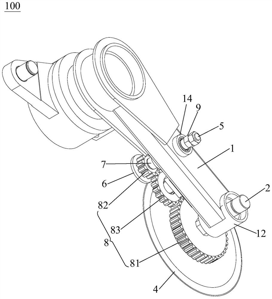
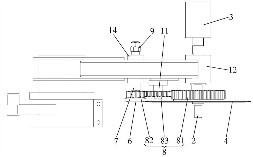
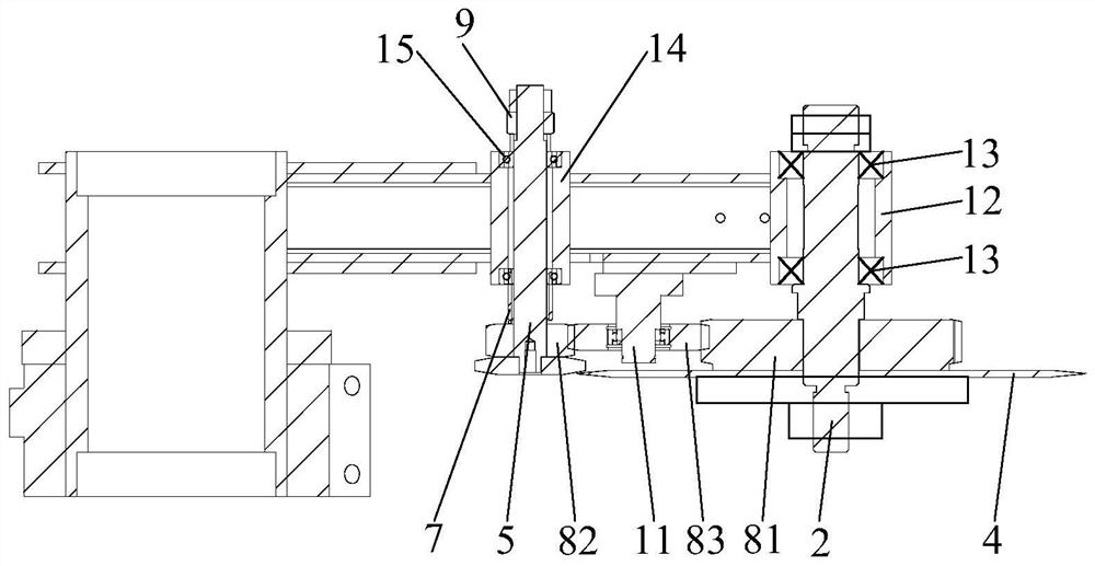
[0020] see Figure 1 to Figure 3 The rotary self-sharpening knife mechanism 100 of the present invention includes a knife arm 1, a first rotating shaft 2, a rotating drive mechanism 3, a cutting knife 4, a second rotating shaft 5, a knife sharpening member 6, an elastic member 7 and a rotating transmission mechanism 8, The first rotating shaft 2 is rotatably installed on the knife arm 1, the output end of the rotating drive mechanism 3 is connected to the first rotating shaft 2, the cutting knife 4 is fixedly connected to the first rotating shaft 2, and the second rotating shaft 5 is movably arranged on the On the knife arm 1, the knife sharpening piece 6 is fixedly connected to one end of the second rotating shaft 5, and the elastic piece 7 is arranged between t...


PUM


Abstract

The invention provides a rotary self-sharpening cutter mechanism. The rotary self-sharpening cutter mechanism comprises a cutter arm, a first rotary shaft, a rotary driving mechanism, a cutter, a second rotary shaft, a sharpening part, an elastic part and a rotating transmission mechanism, the first rotary shaft is rotatably arranged on the cutter arm in a penetrating mode, the output end of the rotary driving mechanism is connected with the first rotary shaft, and the cutter is fixedly connected to the first rotary shaft; the second rotary shaft is movably arranged on the cutter arm, the sharpening part is fixedly connected with one end of the second rotary shaft, the elastic part is arranged between the sharpening part and the cutter arm, and the elastic part is used for driving the sharpening part to be in contact connection with the cutting edge of the cutter; and the rotating transmission mechanism is connected between the first rotary shaft and the second rotary shaft, and the first rotary shaft is driven to rotate through the rotary driving mechanism, so that the rotating transmission mechanism drives the second rotary shaft to rotate. According to the rotary self-sharpening cutter mechanism, the service life of the cutter can be prolonged, and the machining cost is reduced.

Description

technical field [0001] The invention relates to the technical field of extruder line pipe material cutting equipment, in particular to a rotating self-sharpening cutter mechanism. Background technique [0002] Extruder wire pipe cutting equipment is used to cut wire pipes. The wire pipe cutting equipment has a knife arm rotating cutting mechanism for cutting wire pipes. This mechanism usually includes a chassis, a knife feed cylinder and a knife arm. One end of the knife cylinder is rotatably connected to the chassis through a rotating shaft, the other end of the knife feed cylinder is rotatably connected to one end of the knife arm, the middle part of the knife arm is rotatably connected to the chassis through a rotating shaft, and the other end of the knife arm is provided with a cutter. The knife arm is driven to rotate through the knife feed cylinder, so that the cutter of the knife arm can cut the wire pipe. However, the service life of the cutter is short, only about ...

Claims


Application Information

Patent Timeline
IPC IPC(8): B24B3/46B24B3/36B24B47/12B24B41/04B26D7/12
CPCB24B3/46B24B3/368B24B47/12B24B41/04B26D7/12
Inventor 刘洋杨林郑小亮李卓
Owner DEKEMO HUADA MECHANICAL DONGGUAN
Why Eureka
Try Eureka