Concentric common-battery magnetic electricity device

An electrical device, electromagnetic technology, applied in the direction of electromechanical devices, electrical components, magnetic circuit shape/style/structure, etc., can solve the problems of energy loss, accretionary reluctance kinetic energy loss, low power generation efficiency, etc.

Inactive Publication Date: 2019-03-05
YUZEN SUSTAINABLE ENERGY PTE LTD +1
View PDF4 Cites 0 Cited by
  • Summary
  • Abstract
  • Description
  • Claims
  • Application Information

AI Technical Summary

Problems solved by technology

[0003] But in practical application, there are some problems. For example, when it is applied to the motor, affected by the configuration of its coil group and magnetic group, the coil group will still be cut by the rotating magnetic group, which will generate induced electromotive force, so that the coil group needs to be large. The input power is enough to drive, causing unnecessary energy loss
[0004] Another example is when it is applied to a generator, when the coil group is connected to a load to generate current, the coil group will be induced and magnetized to become an electromagnet, and the two ends of the coil group and the magnetic group will produce a magnetic stress phenomenon in the opposite direction of motion. It is opposite to the direction of motion and is reluctance, so there will be

Method used


Image

  • Concentric common-battery magnetic electricity device
  • Concentric common-battery magnetic electricity device
  • Concentric common-battery magnetic electricity device

Examples


Embodiment Construction

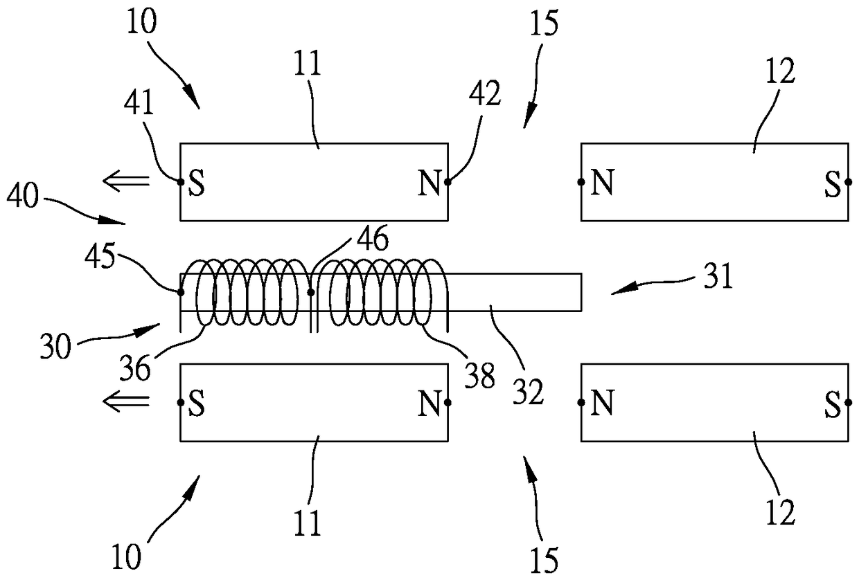
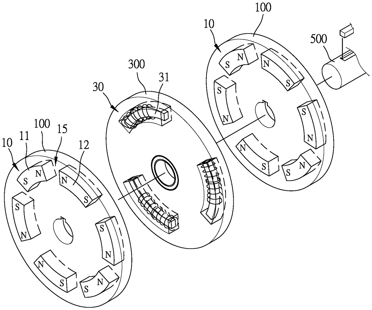
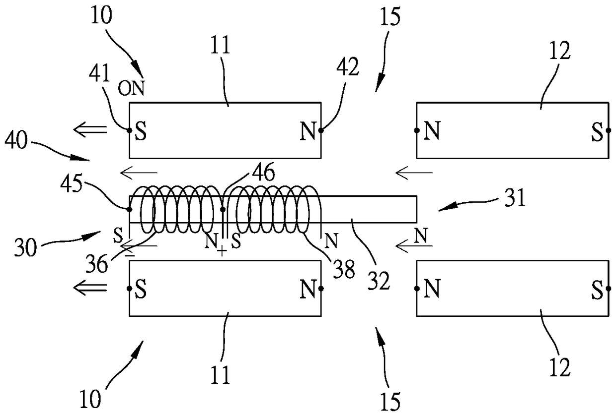
[0050] In order to further understand the structure, features and other purposes of the present invention, some preferred embodiments of the present invention are listed below, and are described in detail with reference to the drawings, so that those skilled in the art can implement them in detail.

[0051] The present invention is a concentric co-electromagnetic device. Among the specific embodiments of the present invention and its components illustrated in the accompanying drawings, all the information about front and rear, left and right, top and bottom, upper and lower, and horizontal and vertical References are made for convenience of description only and do not limit the invention, nor its components, to any position or orientation in space. The dimensions specified in the drawings and description can be changed according to the design and requirements of the specific embodiments of the present invention without departing from the patent scope of the present invention. ...


PUM


Abstract

The invention discloses a concentric common-battery magnetic electricity device, which consists of at least two magnetic column groups, at least one parallel coil column group arranged between opposite magnetic column groups, and at least one inductive switch group, wherein each magnetic column group consists of a first magnetic element and a second magnetic element, and the first magnetic elementand the second magnetic element are magnetized in a motion direction and have a magnetic gap; the coil column group consists of at least one coil, wherein each coil element is provided with a magnetizer, and the length of the magnetizer is length obtained by adding one magnetic element and one magnetic gap; the magnetizer is independently provided with an electricity supply coil connected with apower supply, and an inductance coil connected with a load on one side corresponding to a motion direction leaving end; and the inductive switch group can control whether the electricity supply coil of the coil column group supplies electricity or not. Therefore, a purpose that rotation speed is increased in a whole process can be realized, output power and emitted electric power can be further improved so as to improve the energy conversion efficiency of the device, and the structure is fully utilized.

Description

technical field [0001] The invention relates to the technical field of a magnetoelectric device, in particular to a concentric co-electromagnetic device with both power generation and electromotive functions. Background technique [0002] Generally, no matter whether it is a motor or a generator, a magnetoelectric device is usually used to act. It is mainly composed of two magnetic groups and a coil group that can move relative to each other as a rotor and a stator. Taking the motor as an example, the coil group is intermittently The way of feeding electricity makes it an electromagnet, which can generate repelling and attracting magnetic forces relative to the magnetic group, thereby driving the rotor to rotate at high speed. As for the generator, the external force drives the rotor to rotate at a high speed, so that the coil group generates electricity due to the magnetic field line cutting; [0003] But in practical application, there are some problems. For example, when...

Claims


Application Information

Patent Timeline
IPC IPC(8): H02K1/06
CPCH02K1/06H02K99/10H02K99/20H02K2213/03
Inventor 许永顺许名俊许文毓
Owner YUZEN SUSTAINABLE ENERGY PTE LTD
Why Eureka
Try Eureka