

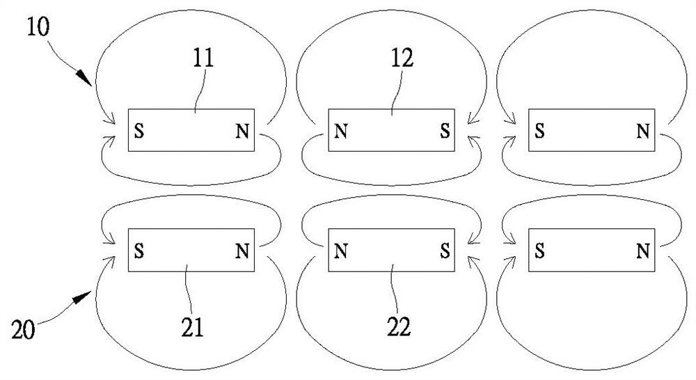
High flux magnetic group device
A technology of high magnetic flux and magnetic group, applied in the electromagnetic field, can solve the problems of insufficient utilization, ineffective utilization of magnetic current, and reduced utilization rate of magnetic lines of force, so as to improve energy conversion efficiency, improve practicability, and reduce dynamic losses. Effect
- Summary
- Abstract
- Description
- Claims
- Application Information
AI Technical Summary
Problems solved by technology
Method used
Image

Examples
Embodiment Construction
[0049] In order to further understand the structure, features and other purposes of the present invention, some preferred embodiments of the present invention are listed below, and are described in detail with reference to the drawings, so that those skilled in the art can implement them in detail.
[0050] The present invention is a high-flux magnetic group device. Among the specific embodiments of the present invention and its components illustrated in the accompanying drawings, all about front and rear, left and right, top and bottom, upper and lower, and horizontal and vertical The references are for convenience of description only, and do not limit the present invention, nor limit its components to any position or spatial orientation. The dimensions specified in the drawings and description can be changed according to the design and requirements of the specific embodiments of the present invention without departing from the patent scope of the present invention.
[0051] ...
PUM
 Abstract
Description
Claims
Application Information