A-column anti-collision structure

A support plate and flanging technology, applied in the field of body-in-white, can solve the problems of large deformation of A-pillars, poor connection neutrality, and insufficient load distribution, and achieve the effect of improving safety and reducing deformation.

Pending Publication Date: 2021-12-10
CHINA FIRST AUTOMOBILE
View PDF8 Cites 0 Cited by
  • Summary
  • Abstract
  • Description
  • Claims
  • Application Information

AI Technical Summary

Problems solved by technology

In the traditional structure, the connection between the inner support plate and the outer support plate of the A-pillar is poor, so that the load transmitted by the shogun cannot be effectively dispersed, so the deformation of the A-pillar from top to bottom door opening is relatively large

Method used


Image

  • A-column anti-collision structure
  • A-column anti-collision structure
  • A-column anti-collision structure

Examples


Embodiment

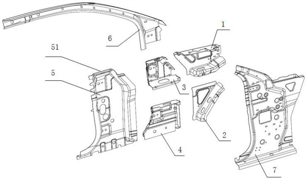
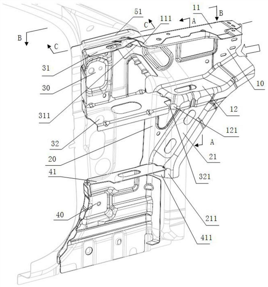
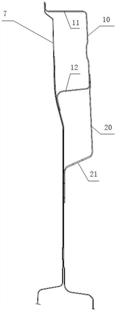
[0040] Such as figure 1 , figure 2 As shown, an A-pillar anti-collision structure consists of an A-pillar outer upper support plate 1, an A-pillar outer lower support plate 2, an A-pillar inner upper support plate 3, an A-pillar inner lower support plate 4, an A-pillar reinforcement plate 5, The A-pillar upper side sill 6 and the A-pillar inner panel 7 are formed. The A-pillar outer upper support plate 1 and the A-pillar outer lower support plate 2 are welded to form sub-assemblies, placed outside the A-pillar reinforcement plate 5, and form two closed cavity structures with the A-pillar inner plate for receiving and transmitting impact loads, such as Figure 4 shown.

[0041] The upper outer support plate 1 of the A-pillar is a U-shaped structure, and the main anti-collision surface 10 of the upper outer support plate 10 of the A-pillar is the bottom surface of the upper outer support plate 1 of the A-pillar. The flange 11 and the second flange 12 of the outer upper supp...


PUM


Abstract

The invention discloses an A-column anti-collision structure which is composed of an A-column external upper supporting plate, an A-column external lower supporting plate, an A-column internal upper supporting plate, an A-column internal lower supporting plate, an A-column reinforcing plate, an A-column upper edge beam and an A-column inner plate. After the A-column external upper supporting plate and the A-column external lower supporting plate are welded to form a sub-assembly, the sub-assembly is installed on the outer side of the A-column reinforcing plate; the A-column external upper supporting plate and the A-column external lower supporting plate are respectively welded with the A-column inner plate to form two closed cavity structures; the A-column internal upper supporting plate, the A-column external upper supporting plate and the column reinforcing plate are welded; the A-column internal lower supporting plate, the A-column external lower supporting plate and the A-column reinforcing plate are welded; the upper part of the A-column reinforcing plate is separately arranged in the middle area of the A-column upper edge beam and the A-column inner plate for three-layer spot welding. The load which is upwards transmitted to the A column through the upper support structure is transmitted and dispersed through the path, the centering performance of the inner supporting plate and the outer supporting plate is good, and the deformation resistance of the A column is enhanced.

Description

technical field [0001] The invention belongs to the technical field of body-in-white, in particular to an A-pillar anti-collision structure. Background technique [0002] In a frontal collision, the collision load received by the front end of the vehicle is transmitted backwards through two paths, one is the downward path and the rearward transmission through the front longitudinal beam, and the other is the upward transmission through the upper support structure (hereinafter referred to as Shotgun) parallel to the longitudinal beam. to the A-pillar. With the continuous improvement of various collision regulations, more stringent conditions such as the increase of collision speed and the reduction of collision overlap, the load transmitted upward to the A-pillar is also increasing, so the carrying capacity of the A-pillar also needs to be improved. Otherwise, the deformation of the A-pillar will cause the door to be unable to open, the windshield to be crushed, and the fron...

Claims


Application Information

Patent Timeline
IPC IPC(8): B62D25/04
CPCB62D25/04
Inventor 刘业峰朱晓亮陈才温泉宋子利丁宇纪延飞
Owner CHINA FIRST AUTOMOBILE
Why Eureka
Try Eureka