Method for swash suppression of adjustable liquid tank

An adjustable, liquid tank technology, applied in the field of ships and ocean engineering, can solve problems such as pressure rise and component damage safety accidents, and achieve the effects of prolonging life, protecting dampers, and reducing strength requirements

Pending Publication Date: 2021-12-10
JIANGSU OCEAN UNIV
View PDF8 Cites 2 Cited by
  • Summary
  • Abstract
  • Description
  • Claims
  • Application Information

AI Technical Summary

Problems solved by technology

At present, the common sloshing methods of changing the structural shape of the liquid tank can only reduce the local sloshing impact pressure, but the pressure rise is likely to occur in other positions, and the method of setting a fixed structure is very likely to transfer the impact pressure of the liquid to the component, causing damage to the component and resulting in a safety accident
At the same time, the method of changing the structural shape of the tank or setting up fixed components can only change the first-order natural frequency of the liquid in the tank from one fixed value to another, and most of them reduce the first-order natural frequency. The change of tank liquid loading rate, such as the tanker fuel tank, the first-order natural frequency of the liquid in the tank will decrease with the decrease of the liquid loading rate. In actual working conditions, low-frequency external excitations often appear with high energy, which is likely to be accompanied by Under the co-occurrence of a certain liquid loading rate and external excitation frequency, the liquid in the cabin resonates
Therefore, the effect of fixing the structure and components on changing the first-order natural frequency of the liquid in the tank to achieve the effect of damping the sloshing effect needs to be improved under certain working conditions.

Method used


Image

  • Method for swash suppression of adjustable liquid tank
  • Method for swash suppression of adjustable liquid tank
  • Method for swash suppression of adjustable liquid tank

Examples


Embodiment

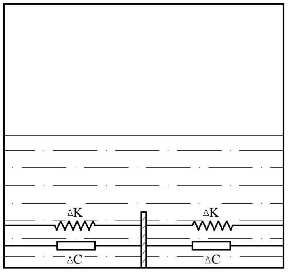
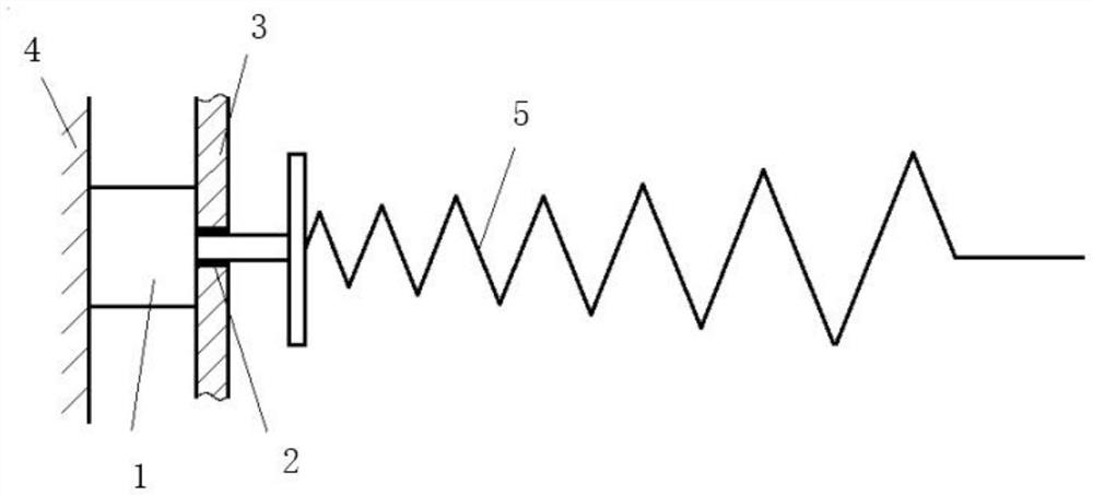
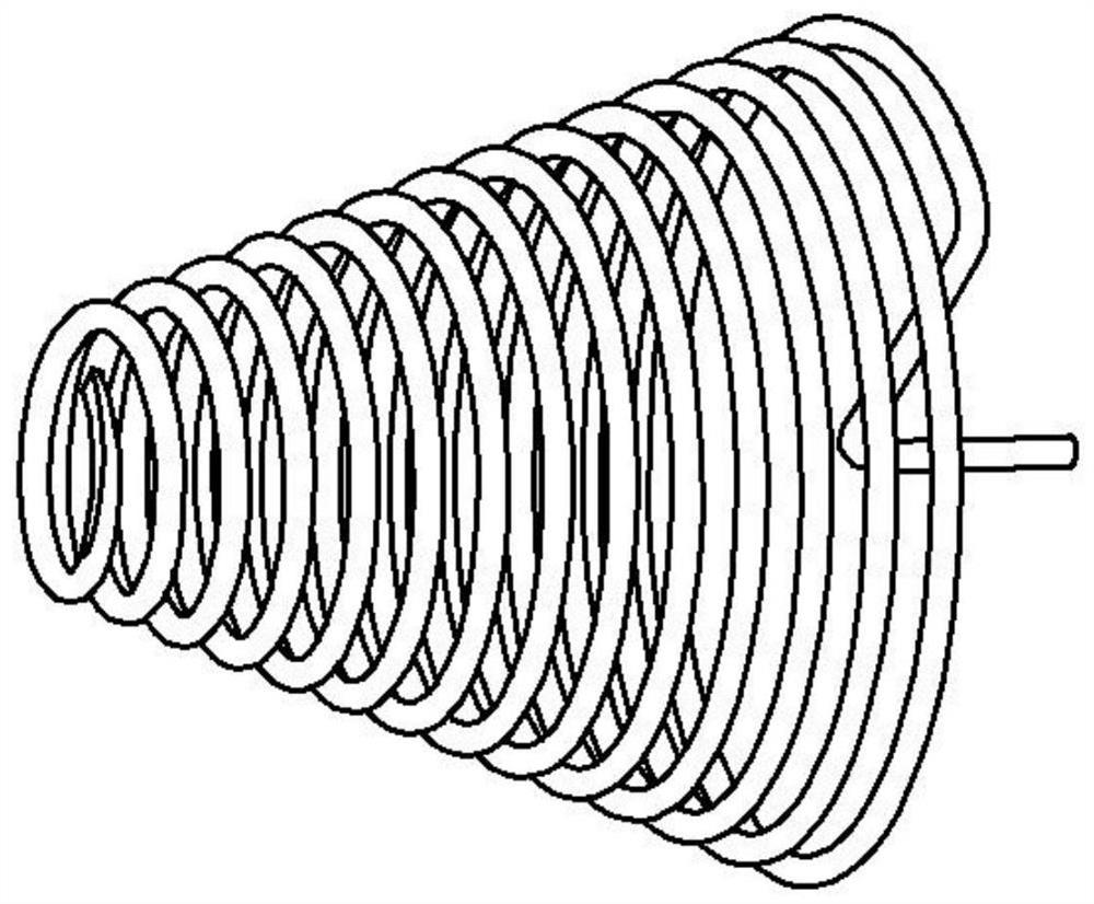
[0020] Example: see Figure 1-3 , the present invention provides a technical solution: a method for adjusting the sloshing of the liquid tank, the specific method is as follows:

[0021] One or more longitudinal bulkheads distributed intermittently along the length of the tank are arranged at the bottom of the tank, and the lateral movement of the longitudinal bulkhead is realized by connecting with the slide rail along the ship’s width direction, and connected with the bulkhead through springs and dampers, according to For the monitoring of the liquid loading rate of the tank and the external excitation, adjust the parameters of the spring and damper so that the actual resonance frequency of the liquid in the tank is far away from the external excitation frequency during the sloshing process of the tank. Under the joint action of the damper, the energy of liquid sloshing is absorbed and dissipated, thereby reducing the impact pressure on the tank wall as a whole.

[0022] Th...


PUM


Abstract

The invention discloses a method for swash suppression of an adjustable liquid tank. One or more longitudinal partition plates distributed discontinuously are arranged at the bottom of the liquid tank in the length direction of the ship, a plurality of sliding rails are arranged in the transverse direction, and the longitudinal partition plates are connected with the sliding rails to move in the width direction of the ship. The longitudinal partition plate is connected with the bulkhead through a spring and a damper. The stiffness coefficient of the spring and the damping coefficient of the damper can be adjusted in real time, parameters of the spring and the damper are adjusted according to the liquid carrying rate of the liquid tank and monitoring of external excitation, the actual first-order resonance frequency of liquid in the tank is made to be far away from the external excitation frequency, and resonance is prevented. Meanwhile, when the liquid in the tank sloshes, the energy of liquid sloshing can be absorbed and dissipated under the combined action of the longitudinal partition plate, the spring and the damper, so that the impact pressure borne by the whole wall face of the liquid tank is reduced, and the service life of the longitudinal partition plate is prolonged. Therefore, according to the scheme, the probability of safety accidents caused by sloshing of the liquid tank is reduced, and the ship traveling safety is guaranteed.

Description

technical field [0001] The invention relates to the field of ships and marine engineering, in particular to a method for controlling sloshing in an adjustable liquid tank. Background technique [0002] As one of the hot issues in the scientific and engineering circles, the problem of tank sloshing has been widely concerned and researched by researchers and engineers from all walks of life. Especially with the development and application of LNG ships, the problem of sloshing has further highlighted its importance in ship design and ship design. The importance of safety. For the hull structure, the impact pressure caused by liquid sloshing has the greatest impact on the wall when the liquid in the tank resonates. Therefore, how to reduce the impact pressure caused by the sloshing liquid and how to keep the actual first-order natural frequency of the liquid in the tank away from the external excitation frequency becomes The focus of research on sway control problems and ship d...

Claims


Application Information

Patent Timeline
Patent Type & Authority Applications(China)
IPC IPC(8): B63B25/12
CPCB63B25/12
Inventor 邹昶方王晨屹朱家演缪泉明袁晓楠
Owner JIANGSU OCEAN UNIV
Why Eureka
Try Eureka