


Quick Research
Generate reliable direction feasibility study reports for your R&D in just a few steps.

Technical Q&A
Discover and master advanced knowledge NOW. Basics, ideas, possibilities, all at once.

Find Solutions
As an expert in R&D theories, this can generate solutions to your technical problems instantly.

Evaluate Feasibility
Analyze your overall solution with one click, know your potential R&D risks in advance.

Monitor Landscape
Get weekly tech updates, stay abreast of the latest tech innovations and key insights.
Combined vehicle-mounted pneumatic conveying device for bulk material conveying
A pneumatic conveying and combined technology, which is applied in the direction of freight vehicles, conveying bulk materials, conveyors, etc., can solve the problems of idle resources and waste, and achieve the effect of expanding the use
- Summary
- Abstract
- Description
- Claims
- Application Information
AI Technical Summary
Problems solved by technology
Method used
Image

Examples
Embodiment 1
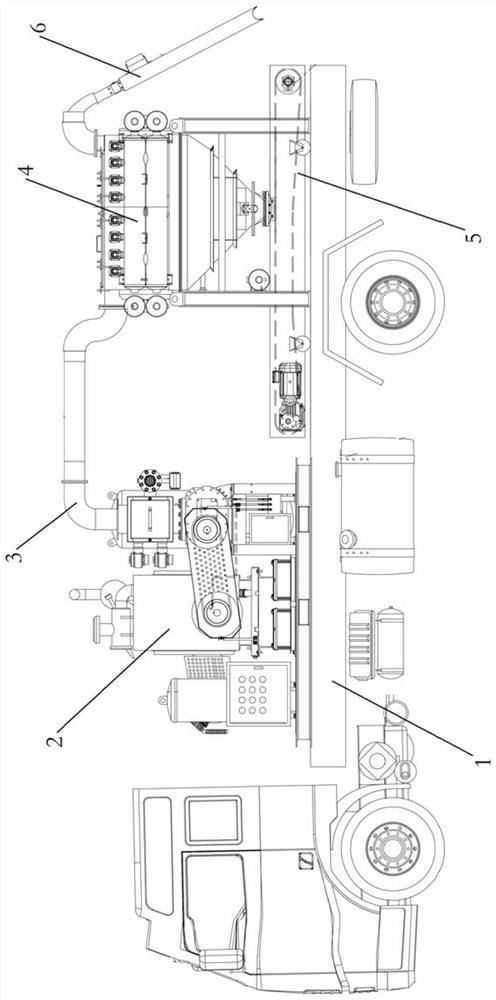
[0027] Such as figure 1 Shown:
[0028] A combined vehicle-mounted pneumatic conveying device for bulk material transportation, including an air-driven power module 2 arranged on a car chassis 1, a mesh separation bin 4 and a belt conveyor 5, and the air-driven power module 2 is connected to the air-driven power module through a hose 3 The exhaust pipe of the mesh separation bin 4 is connected, the feeding pipe of the mesh separation bin 4 is connected with a suction nozzle 6, and a belt conveyor 5 is arranged below the discharge gate valve at the bottom of the mesh separation bin 4 .
[0029] In the present embodiment, the automobile chassis can adopt a general-purpose truck, and can adopt a truck with a compartment length of 4.8 meters.
[0030] This embodiment is mainly used to clean up the material accumulated at the bottom of a single bucket elevator or elevator shaft, and to deal with the accumulated material in deep wells or pipeline elbows. When used:
[0031] Step 1...
Embodiment 2
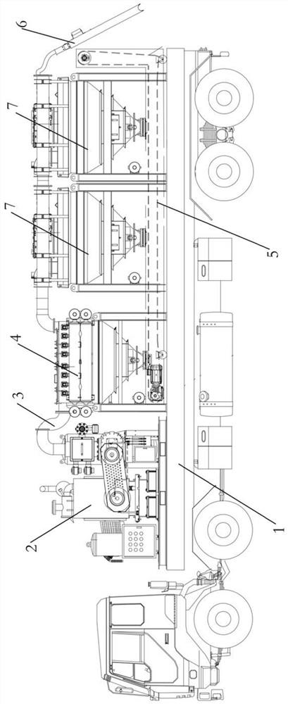
[0037] Such as figure 2 Shown:
[0038] The structure of this embodiment is basically the same as that of the embodiment, the difference is that this embodiment also includes two air-induced mechanical separation bins 7 (the number of air-induced mechanical separation bins 7 can also be multiple), two air-induced mechanical separation bins 7 The discharge pipes of the mechanical separation bin 7 are respectively connected with the feed pipes of the mesh separation bin 4 . The feed pipes of the air-induced mechanical separation chamber 7 are respectively connected with the suction nozzles 6 . The conveyor 5 is located below the mesh separation bin 4 and the air-induced mechanical separation bin 7 .
[0039] In this embodiment, the chassis of the car can be a general-purpose truck, or a truck with a compartment length of 9.6 meters.
[0040] When this embodiment is used to remove a large amount of materials in a confined space, when used:
[0041] Step 1: Hoist the air-driv...
Embodiment 3
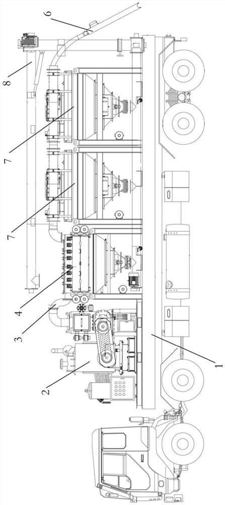
[0047] Such as image 3 and Figure 5 Shown:
[0048]The structure of this embodiment is basically the same as that of Embodiment 2, the difference being that a three-stage screw feeder 8 is provided below the mesh separation bin 4 and the air-induced mechanical separation bin 7 in this embodiment. The three-stage screw feeder 8 is used for easily floating materials. The three-stage screw feeder 8 includes a first-stage screw feeder 801, a second-stage screw feeder 802, and a third-stage screw feeder 803. The first-stage screw feeder 801 is located in the air-induced mechanical separation bin 7 The bottom of the vehicle is used to convey the material to the rear of the vehicle; the second-stage screw feeder 802 is installed vertically at the rear of the vehicle, and the second-stage screw feeder 802 is connected to the first-stage screw feeder 801 for lifting materials; The third-stage screw feeder 803 is located on the roof, and the third-stage screw feeder 803 is connecte...
PUM
 Abstract
Description
Claims
Application Information
 - R&D Engineer
- R&D Manager
- IP Professional
- Industry Leading Data Capabilities
- Powerful AI technology
- Patent DNA Extraction
Browse by: Latest US Patents, China's latest patents, Technical Efficacy Thesaurus, Application Domain, Technology Topic, Popular Technical Reports.
© 2024 PatSnap. All rights reserved.Legal|Privacy policy|Modern Slavery Act Transparency Statement|Sitemap|About US| Contact US: help@patsnap.com