Glass bead overheating screening device
A screening device and glass bead technology, applied in the field of glass bead overheating screening device, can solve the problems of low work efficiency, high temperature, troublesome operation, etc., and achieve the effect of high work efficiency and increased cooling efficiency
- Summary
- Abstract
- Description
- Claims
- Application Information
AI Technical Summary
Problems solved by technology
Method used
Image
Examples
Embodiment 1
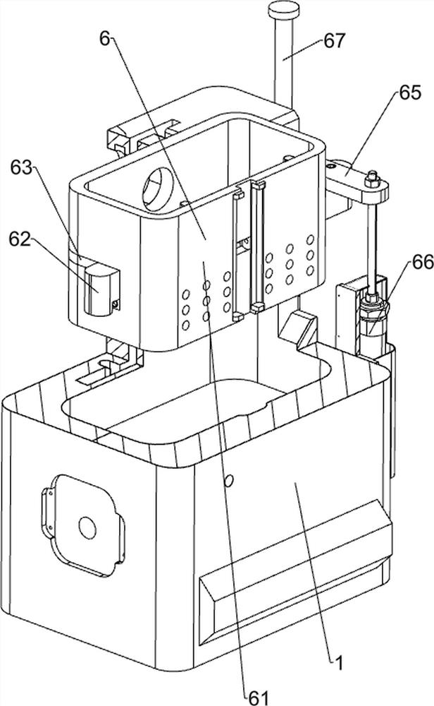
[0043] A glass bead overheating screening device, such as Figure 1-Figure 9 As shown, it includes a heat-resistant bottom box 1, a supporting bottom plate 2, a charging box 3, a feeding pipe 31, a heating button 41, a feeding button 42, a liquid replacement button 43, a heating module 5, a temperature sensor 51, and a lifting mechanism 6 and the cooling mechanism 7, the bottom of the heat-resistant bottom box 1 is fixedly connected with the support bottom plate 2, the upper left side of the heat-resistant bottom box 1 is fixedly connected with the charging box 3, and the charging box 3 is connected with the heat-resistant bottom box 1. The material pipe 31 is fixedly connected with a heating button 41 on the upper middle part of the front side of the heat-resistant bottom box 1, and is fixedly connected with a discharge button 42 on the upper middle part of the front side of the heat-resistant bottom box 1. The discharge button 42 is located on the right side of the heating bu...
Embodiment 2
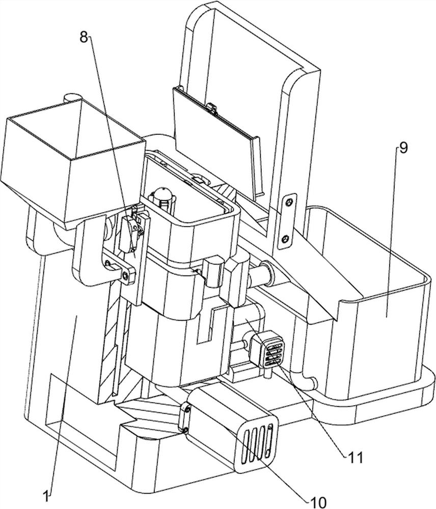
[0048] On the basis of Example 1, such as Figure 10-Figure 17 As shown, it also includes a stopper mechanism 8, and the stopper mechanism 8 includes a limit baffle 81, a first positioning guide rod 82, a first return spring 83, a feed baffle 84, a limit cross bar 85, and a limit bottom. Block 86, positioning roller 87, positioning post 88, spring block 89, compression spring 810, limit block 811, limit bottom post 812, second positioning guide rod 813, second return spring 814, jacking bottom Block 815 and limit spring 816, the left part in the heat-resistant bottom box 1 is fixedly connected with the first positioning guide rod 82 symmetrically front and back, and the first positioning guide rod 82 on the front and rear sides is slidably provided with a limit baffle plate 81, the first The positioning guide rod 82 is wound with a first return spring 83, one end of the first return spring 83 is connected with the limit baffle plate 81, and the other end is connected with the ...
Embodiment 3
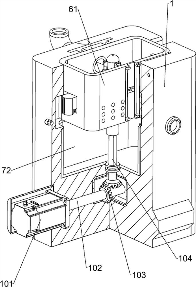
[0053] On the basis of embodiment 1 and embodiment 2, such as Figure 18-Figure 21 As shown, a stirring mechanism 10 is also included, and the stirring mechanism 10 includes a servo motor 101, a drive shaft 102, a reversing bevel gear assembly 103, a hexagonal drive vertical shaft 104, a hollow rotating shaft 105, a positioning slider 106, a hinged connecting rod 107, Positioning connecting plate 108 and fourth return spring 109, servo motor 101 is provided on the lower side of the front part of heat-resistant bottom box 1, and drive shaft 102 is connected to the output shaft of servo motor 101, and the middle side of immersion box 72 is rotatably provided with hexagonal drive vertical shaft 104, a reversing bevel gear assembly 103 is provided between the lower part of the hexagonal driving vertical shaft 104 and the rear part of the driving shaft 102, and a hollow rotating shaft 105 is provided on the middle side of the lower part of the lifting bottom box 61, and the hollow r...
PUM
 Abstract
Description
Claims
Application Information
 - R&D
- Intellectual Property
- Life Sciences
- Materials
- Tech Scout
- Unparalleled Data Quality
- Higher Quality Content
- 60% Fewer Hallucinations
Browse by: Latest US Patents, China's latest patents, Technical Efficacy Thesaurus, Application Domain, Technology Topic, Popular Technical Reports.
© 2025 PatSnap. All rights reserved.Legal|Privacy policy|Modern Slavery Act Transparency Statement|Sitemap|About US| Contact US: help@patsnap.com


