Optical fiber drawing device capable of effectively adjusting traction force and improving quality of finished optical fiber product

A traction, optical fiber technology, applied in the field of optical fiber equipment, can solve problems such as affecting the drawing quality, the belt slipping easily, and affecting the drawing accuracy.

Inactive Publication Date: 2021-12-10
吴建龙
View PDF0 Cites 0 Cited by
  • Summary
  • Abstract
  • Description
  • Claims
  • Application Information

AI Technical Summary

Problems solved by technology

[0005] Aiming at the deficiencies of the prior art, the present invention provides an optical fiber drawing device that can effectively adjust the traction force and improve the quality of the finished optical fiber. It has the advantages that the tension force of the belt can be adjusted according to the demand and the traction force can be adjusted according to different thicknesses of optical fibers. , to solve the problem that some optical fiber drawing machines cannot adjust the tension of the belt, and the tension of the belt will become smaller after a period of use. When the tension is too small, the belt is easy to slip, which will affect the accuracy of drawing. Moreover, the existing wire drawing machine cannot adjust the pulling force according to different thicknesses of optical fibers. If the pulling force is too low, it will easily lead to bending of the drawing, which seriously affects the quality of the drawing.

Method used


Image

  • Optical fiber drawing device capable of effectively adjusting traction force and improving quality of finished optical fiber product
  • Optical fiber drawing device capable of effectively adjusting traction force and improving quality of finished optical fiber product
  • Optical fiber drawing device capable of effectively adjusting traction force and improving quality of finished optical fiber product

Examples


Embodiment Construction

[0023] The following will clearly and completely describe the technical solutions in the embodiments of the present invention with reference to the accompanying drawings in the embodiments of the present invention. Obviously, the described embodiments are only some, not all, embodiments of the present invention. Based on the embodiments of the present invention, all other embodiments obtained by persons of ordinary skill in the art without making creative efforts belong to the protection scope of the present invention.

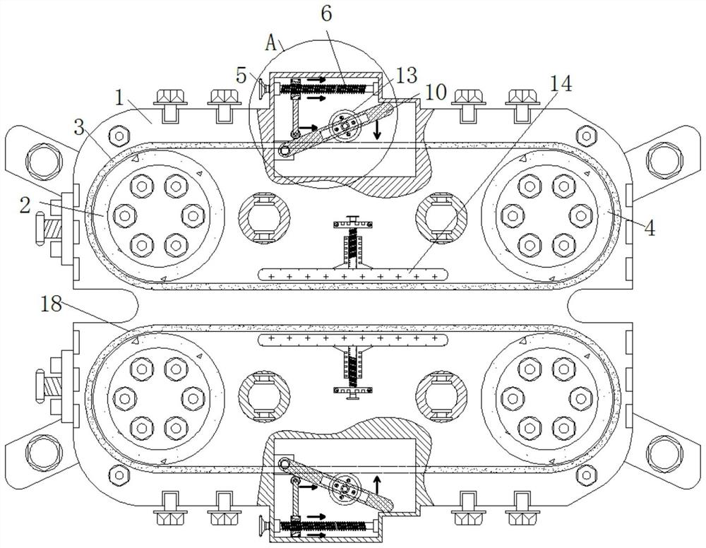
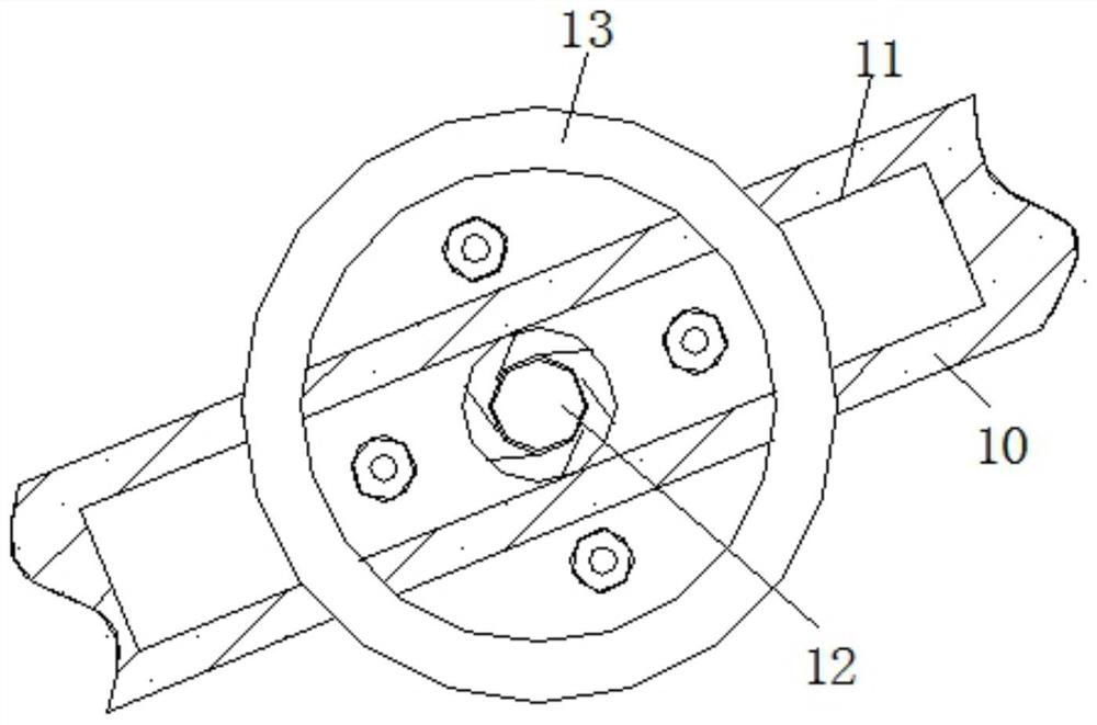
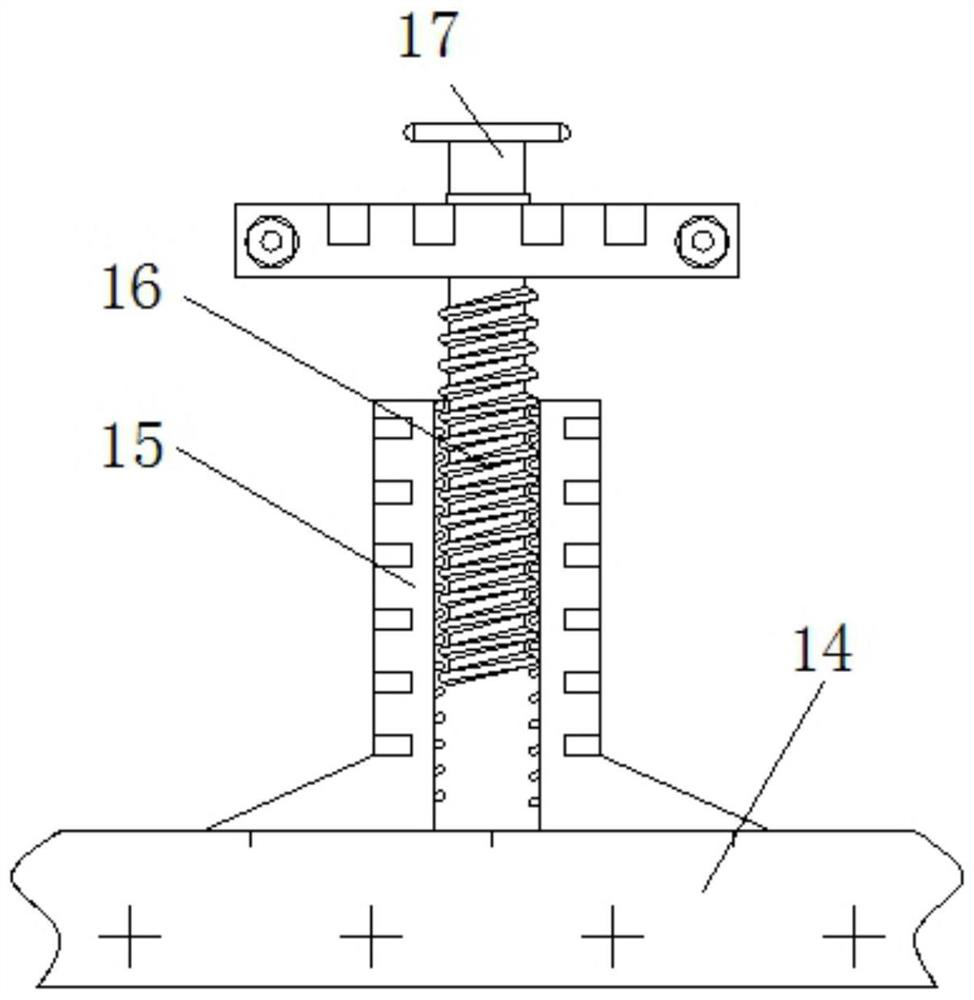
[0024] see Figure 1-4 , an optical fiber drawing device that can effectively adjust the traction force and improve the quality of the finished optical fiber, comprising a base 1, the front structure of the base 1 is symmetrical and the same, the front of the base 1 is movably connected with a driving disk 2, and the left side of the driving disk 2 is connected with a drive Belt one 3, the internal transmission on the left side of belt one 3 is connected with ...


PUM


Abstract

The invention relates to the technical field of optical fiber equipment, and discloses an optical fiber drawing device capable of effectively adjusting traction force and improving the quality of an optical fiber finished product. The optical fiber drawing device comprises a base, the front surface of the base is movably connected with a driving disc, the left side of the driving disc is in transmission connection with a first belt, and the interior of the left side of the first belt is in transmission connection with a driven disc. According to the optical fiber drawing device capable of effectively adjusting the traction force and improving the quality of the optical fiber finished product, a rotary knob is rotated, a sliding block can move left and right on the outer wall of a lead screw, a rolling wheel further drives a movable rod to deflect up and down, and a rotating disc can vertically extrude the first belt, so the effect that the tensioning force of the belt can be adjusted according to needs is achieved. And when a rotating rod is rotated, a fixed block can move up and down on the outer wall of the lead screw, a limiting plate can further move up and down, and the distance between the first belt and a second belt can be changed, so that the effect of adjusting the traction force according to the optical fibers with different thicknesses is achieved.

Description

technical field [0001] The invention relates to the technical field of optical fiber equipment, in particular to an optical fiber drawing device for effectively adjusting traction force and improving the quality of optical fiber finished products. Background technique [0002] As the name implies, optical fiber equipment refers to all equipment that uses optical fiber as the application object, and is called optical fiber equipment. Due to the inherent advantages of optical fiber technology, optical fiber has gradually become the standard basis for all networks, so this makes the optical fiber equipment market extremely competitive. At present, this field There are more than 20 suppliers, and fiber optic equipment generally includes: fiber optic transceivers, fiber amplifiers, fiber sensors, fiber drawing machines, etc. [0003] Existing optical fiber drawing machines cannot adjust the tension of the belt, and the tension of the belt will become smaller after a period of use...

Claims


Application Information

Patent Timeline
Patent Type & Authority Applications(China)
IPC IPC(8): C03B37/03
CPCC03B37/03
Inventor 吴建龙
Owner 吴建龙
Why Eureka
Try Eureka