Check patentability & draft patents in minutes with Patsnap Eureka AI!

Cast-in-place box girder edge protection structure and construction method

A technology of edge protection and box girder, applied in bridges, bridge construction, erection/assembly of bridges, etc., can solve problems such as poor safety effect, and achieve the effect of easy construction, good safety, and improved impact resistance.

Active Publication Date: 2021-12-10
黑龙江省龙建路桥第五工程有限公司
View PDF24 Cites 0 Cited by
  • Summary
  • Abstract
  • Description
  • Claims
  • Application Information

AI Technical Summary

Problems solved by technology

However, after the upper part of the bracket protective railing is impacted, it transmits a horizontal force to the outside of the whole bracket, and the safety effect is poor.

Method used


Image

  • Cast-in-place box girder edge protection structure and construction method
  • Cast-in-place box girder edge protection structure and construction method
  • Cast-in-place box girder edge protection structure and construction method

Examples


Embodiment 1

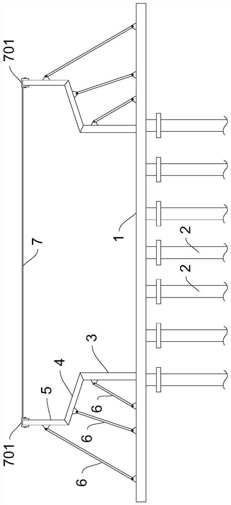
[0048] Please refer to Figure 1 to Figure 4 , shows a cast-in-situ box girder marginal protection structure provided by an embodiment of the present invention, and the structure is as follows.

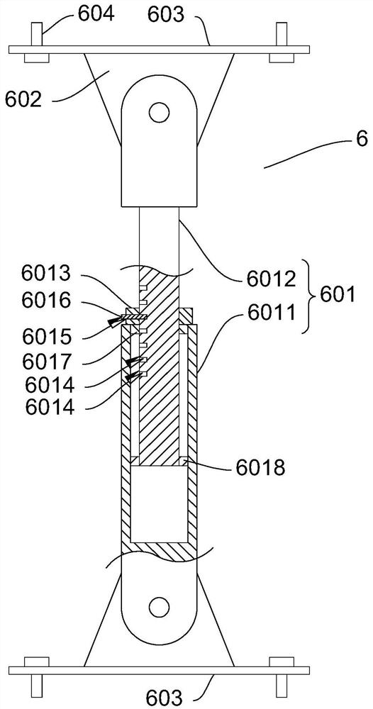
[0049] The embodiment of the present application provides a cast-in-place box girder border protection structure, which includes a main load-bearing beam 1. The top of the formwork 3 is provided with a cantilever support formwork 4, and the top of the cantilever support formwork 4 is provided with a border guardrail 5, and the main support formwork 3, the cantilever support formwork 4 and the border guardrail 5 are respectively connected with a support bar 6, and the bottom of the support bar 6 It is fixedly connected with the main load-bearing beam 1, and the tops of the guardrails 5 on both sides are provided with tension steel ropes 7. combine figure 1 As shown, there are multiple supports 2 for the whole hall, which jointly play a better supporting role for the main load-bearing...

Embodiment 2

[0061] In the second aspect, the embodiment of the present application provides a construction method, which includes the above-mentioned cast-in-place box girder edge protection structure, and further includes the following steps,

[0062] S1. Vertically install the full-wall support 2, the bottom of the full-wall support 2 is inserted into the ground, the adjacent full-wall support 2 is fixedly connected by steel pipes and fasteners, and the main load-bearing beam 1 is installed on the top of the full-wall support 2,

[0063] S2. Fix and install the main support formwork 3, the cantilever support formwork 4 and the border guardrail 5 in sequence, and the border guardrail 5 and the cantilever support formwork 4 are fixed by nailing,

[0064] S3, the bottom of the support bar 6 and the main load-bearing beam 1 are fixed by bolts, and the top of the support bar 6 is fixed to the main support formwork 3, the cantilever support formwork 4 or the edge guardrail 5,

[0065] S4. Ten...


PUM


Abstract

The invention provides a cast-in-place box girder edge protection structure, and relates to the technical field of civil construction. The cast-in-place box girder edge protection structure comprises a main bearing beam, the bottom of the main bearing beam is provided with a full framing, the top of the main bearing beam is provided with a main supporting template, and the top of the main supporting template is provided with a cantilever supporting template; edge protection fences are arranged at the top of the cantilever supporting template; the main supporting formwork, the cantilever supporting formwork and the edge protection fences are connected with supporting rods respectively, the bottoms of the supporting rods are fixedly connected with the main bearing beam, and tensioning steel ropes are arranged on the tops of the edge protection fences on the two sides, and the beneficial effects of being good in safety and convenient to install are achieved. The invention further provides a construction method, through the technical scheme that the full framing, the main bearing beam, the main supporting formwork, the cantilever supporting formwork, the edge protection fences and the supporting rods are installed, and the tensioning steel ropes are installed on the tops of the edge protection fences on the two sides, the construction method has the advantages of being firm and durable and protecting construction safety.

Description

technical field [0001] The invention relates to the technical field of civil construction, in particular to a cast-in-place box girder border protection structure and a construction method. Background technique [0002] A kind of beam in box girder bridge engineering, the interior is hollow, with flanges on both sides of the upper part, similar to a box, hence the name, divided into single box, multi box, etc. The box girder of reinforced concrete structure is divided into prefabricated box girder and cast-in-place box girder. The prefabricated box girder combined with the bridge erecting machine can be erected after the completion of the substructure, which can speed up the progress of the project and save the construction period; the cast-in-place box girder is mostly used for large continuous bridges. Commonly divided by materials, there are two main types, one is prestressed reinforced concrete box girder, and the other is steel box girder. Among them, the prestressed ...

Claims


Application Information

Patent Timeline
IPC IPC(8): E01D21/00E01D2/04
CPCE01D21/00E01D2/04
Inventor 宿天子韩玉超李玉国黄帅张大力肖子鹏曲世忱田雷姜晓岩刘召辉刘长刚
Owner 黑龙江省龙建路桥第五工程有限公司
Features
  • R&D
  • Intellectual Property
  • Life Sciences
  • Materials
  • Tech Scout
  • Unparalleled Data Quality
  • Higher Quality Content
  • 60% Fewer Hallucinations
Learn More