
Equipment state display method and computer readable storage medium

A technology for displaying methods and equipment status, applied in computing, mechanical equipment, lighting and heating equipment, etc., can solve the problem of which component cannot be determined in a short time, save maintenance time and maintenance costs, improve user experience, maintenance time saving effect

Inactive Publication Date: 2021-12-10
GREE ELECTRIC APPLIANCES INC
View PDF5 Cites 0 Cited by
  • Summary
  • Abstract
  • Description
  • Claims
  • Application Information

AI Technical Summary

Problems solved by technology

[0005] In order to solve the technical problem in the prior art that when the state of the device changes, it is impossible to determine which component part is caused by it in a short time, the present invention proposes a display method for the state of the device and a computer-readable storage medium

Method used


Image

  • Equipment state display method and computer readable storage medium
  • Equipment state display method and computer readable storage medium
  • Equipment state display method and computer readable storage medium

Examples


Embodiment Construction

[0026] In order to make the technical problems, technical solutions and beneficial effects to be solved by the present invention clearer, the present invention will be further described in detail below in conjunction with the accompanying drawings and embodiments. It should be understood that the specific embodiments described here are only used to explain the present invention, not to limit the present invention.

[0027] Thus, a feature indicated in this specification will be used to describe one of the features of an embodiment of the present invention, rather than implying that every embodiment of the present invention must have the described feature. Furthermore, it should be noted that this specification describes a number of features. Although certain features may be combined to illustrate possible system designs, these features may also be used in other combinations not explicitly described. Thus, the illustrated combinations are not intended to be limiting unless oth...


PUM


Abstract

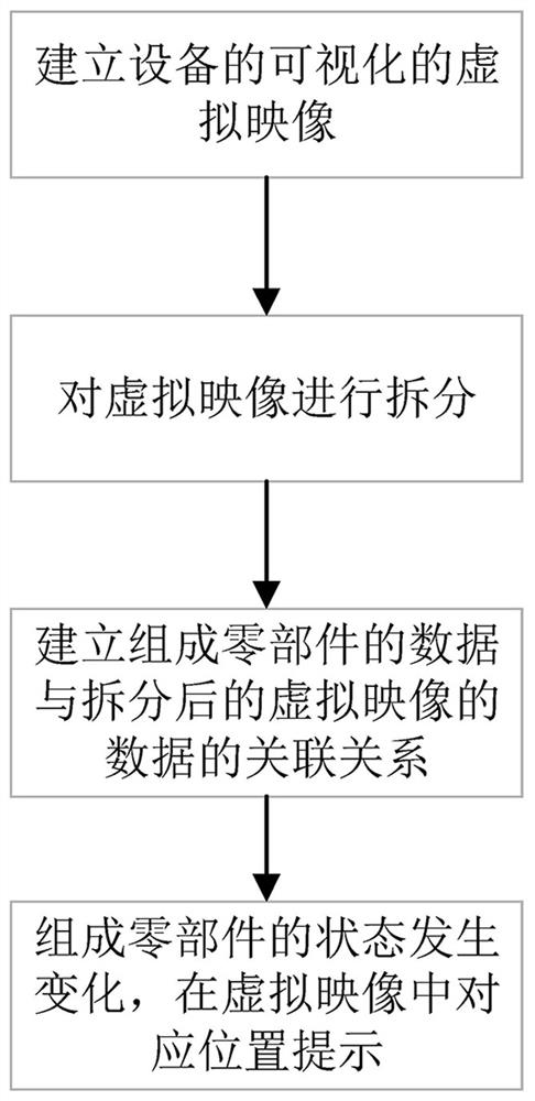
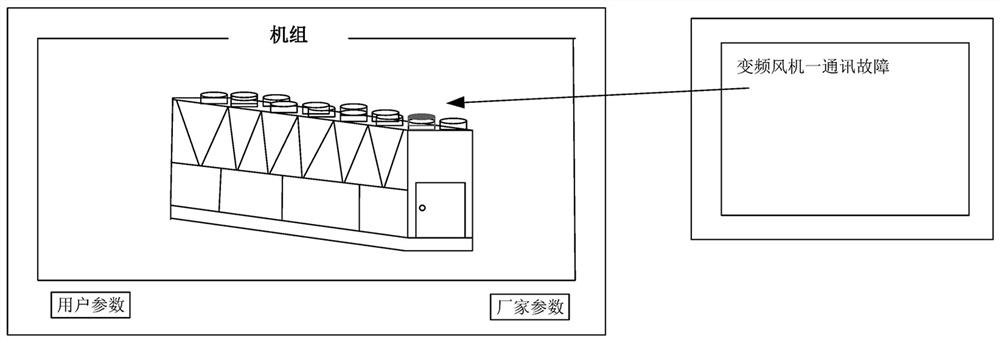
The invention discloses an equipment state display method and a computer readable storage medium. The equipment state display method comprises the following steps of establishing a visual virtual image of equipment; splitting the virtual image according to composition parts of the equipment; establishing an association relationship between the data of the component and the data of the split virtual image; and when the state of the component changes, prompting at a corresponding position in the virtual image according to the association relationship. According to the method, a user can quickly know the structure of the equipment, the positions of corresponding components due to the change of the positioning state, and convenience is provided for overhaul, maintenance and the like.

Description

technical field [0001] The invention relates to the technical field of intelligent processing of equipment information, in particular to a method for displaying equipment status. Background technique [0002] With the development and progress of technology, existing equipment is becoming more and more sophisticated, with more and more functions, and more and more parts and / or related parameters of parts. [0003] Take air conditioners as an example. People are now demanding more and more comfort in their lives. Whether they are at home or traveling in shopping malls, stations and other indoor scenes, they want to place themselves in a space with the most suitable temperature. Therefore, commercial air-conditioning large units need to have more and more functions, the control parameters of the unit also increase, and the unit structure becomes more complicated, which brings greater difficulty to the control and maintenance of the unit to a certain extent. . [0004] For exa...

Claims


Application Information

Patent Timeline
Patent Type & Authority Applications(China)
IPC IPC(8): F24F11/52F24F11/38G06F3/0481G06F3/0488
CPCF24F11/52F24F11/38G06F3/0481G06F3/0488
Inventor 毛凤梅唐政清李辉光陆贵生庞帅帅
Owner GREE ELECTRIC APPLIANCES INC
Learn More