
Static and dynamic load test method suitable for large steel aqueduct structure

A test method, a large-scale technology, applied in the direction of testing material strength by applying repetitive force/pulsation force, testing material strength by applying stable tension/compression, and measuring devices, which can solve the problems affecting the accuracy of load tests, the lack of experimental data, Time-consuming and labor-intensive problems, to achieve the effect of saving test cost, simple loading method, and reliable test results

Pending Publication Date: 2021-12-10
安徽省七星工程测试有限公司
View PDF1 Cites 0 Cited by
  • Summary
  • Abstract
  • Description
  • Claims
  • Application Information

AI Technical Summary

Problems solved by technology

Carrying out the aqueduct load test needs to suspend the normal operation of the aqueduct. This test is time-consuming, laborious, and costly. Generally, the period of the load test is relatively long, resulting in less and incomplete experimental data obtained, which affects the accuracy of the load test.
In addition, the suspension of work has also brought a lot of inconvenience to the use of the aqueduct and the progress of the project

Method used


Image

  • Static and dynamic load test method suitable for large steel aqueduct structure
  • Static and dynamic load test method suitable for large steel aqueduct structure
  • Static and dynamic load test method suitable for large steel aqueduct structure

Examples


Embodiment 1

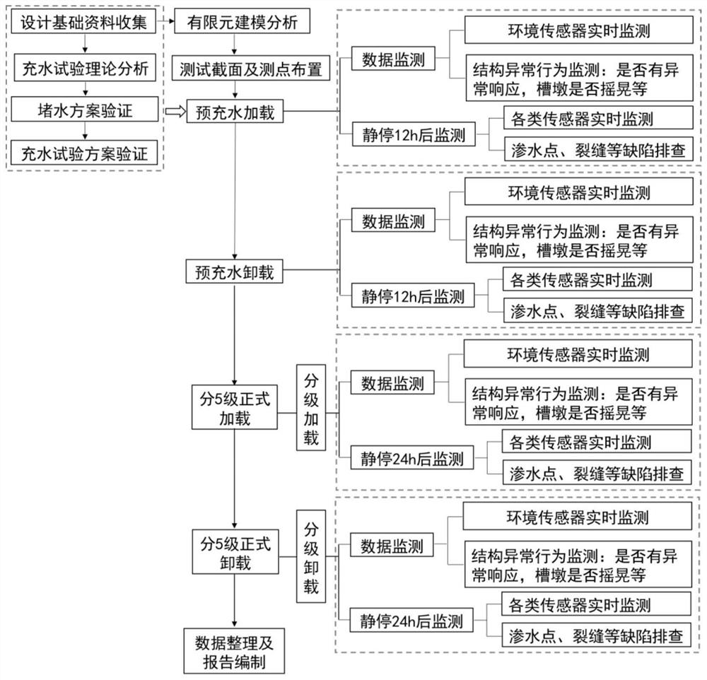
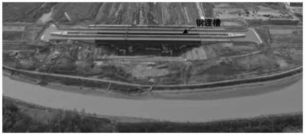
[0045] Embodiment 1 Aqueduct static and dynamic load test process

[0046] For the load test of the aqueduct structure, the test procedure is as follows figure 1 As shown, the static and dynamic information of the steel aqueduct structure is collected, and the data monitoring process is as follows:

[0047] (1) Various monitoring equipment should be arranged in place before formal water injection, that is, start monitoring and recording data.

[0048] (2) After the monitoring equipment is arranged, the monitoring work should be carried out in time, and the changes of each part of the aqueduct should be understood according to the real-time monitoring data. When the monitoring data are within the allowable range of the design, and there is no obvious fluctuation for 1 hour, it means that the structural coordination deformation has been stabilized, and the water filling test can be carried out. The monitoring data at this time can be used as the initial data of the water filli...

Embodiment 2

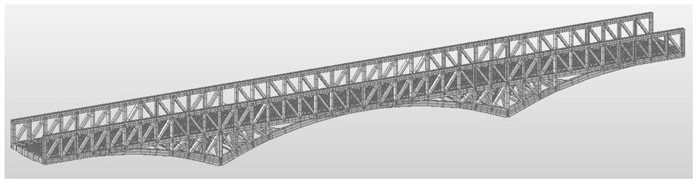
[0054] Embodiment 2 Determination of test section and measuring point

[0055] The selection of the test section and the arrangement of the measuring points are a key step in the early stage of the aqueduct load test. For the steel aqueduct structure, the purpose of the water filling test is to test whether the stress of the key section of the aqueduct structure meets the requirements of the code. According to the finite element model analysis, Focus on selecting the most unfavorable force-bearing position of the structure as the test section. The layout of measuring points should follow the following principles:

[0056] (1) Under the design load, the test section with the maximum positive bending moment;

[0057] (2) Under the design load, the test section with the maximum negative bending moment;

[0058] (3) Under the design load, the maximum tensile and compressive stress positions of the rigid aqueduct;

[0059] (4) Displacement monitoring and measuring points for aqu...


PUM


Abstract

The invention discloses a static and dynamic load test method suitable for a large steel aqueduct structure, which aims at a load test of the aqueduct structure, a static load test and a dynamic load test of the aqueduct structure are simultaneously carried out, and static and dynamic information of the steel aqueduct structure is simultaneously acquired in water filling and drainage test working conditions of the aqueduct; the test point arrangement, the loading mode, the sensor selection, the test content and the like of the test are specifically arranged, the static and dynamic load test of the structure is effectively realized, and the device has important engineering practical value. The load test of the aqueduct can be completed through the water filling test, and the static load test and the dynamic load test are simultaneously carried out and monitored, so that most time is saved, the influence of pause on a project is reduced, and the test cost is saved.

Description

technical field [0001] The invention relates to the technical field of aqueduct quality detection, in particular to a static and dynamic load test method suitable for large-scale steel aqueduct structures. Background technique [0002] In recent years, due to the development and demand of navigable water transport, many large-scale aqueduct structures have been built at home and abroad, but these aqueducts are mostly based on concrete beam systems, and steel structure aqueducts are rarely used. Compared with concrete structure aqueducts, large-scale steel structure aqueducts are more difficult in design, construction and later operation and maintenance. The entire structural system of the steel aqueduct is complex. Under the joint action of disaster factors such as environmental erosion, material aging, long-term effects of load, and fatigue effects, it will inevitably lead to damage accumulation and resistance attenuation of the structure and system, and may lead to disaste...

Claims


Application Information

Patent Timeline
IPC IPC(8): G01N3/10G01N3/36
CPCG01N3/10G01N3/36G01N2203/0003G01N2203/0005G01N2203/0048G01N2203/0075G01N2203/0694
Inventor 陈发军付书林程勇刚李迪鲍大春叶刘克张菲却杨玉盟孔凡子陈翔张昊葛磊沈达
Owner 安徽省七星工程测试有限公司
Learn More