A low temperature and high stability support structure for reflective grating installation

A technology with high stability and support structure, which is applied in the field of optical engineering, can solve problems such as the inability to control the surface shape of optical elements well, the complex support structure at low temperature, and the impact on system performance, etc., to achieve temperature stability, simple structure, and easy assembly The effect of low process requirements

Active Publication Date: 2022-08-05
XI'AN INST OF OPTICS & FINE MECHANICS - CHINESE ACAD OF SCI
View PDF8 Cites 0 Cited by
  • Summary
  • Abstract
  • Description
  • Claims
  • Application Information

AI Technical Summary

Problems solved by technology

[0005] In order to solve the problem that most of the low-temperature support structures of reflective gratings for low-temperature environments are relatively complex and cannot well control the surface shape changes of optical elements, which will cause the system interference fringes to be inclined and bent, and the modulation degree will be reduced, which will affect the system performance. The present invention provides A low-temperature high-stability support structure for reflective grating installation

Method used


Image

  • A low temperature and high stability support structure for reflective grating installation
  • A low temperature and high stability support structure for reflective grating installation
  • A low temperature and high stability support structure for reflective grating installation

Examples


Embodiment Construction

[0040] In order to make the above purposes, characteristics, and advantages of the present invention more obvious, the following combined instructions have a detailed explanation of the specific embodiment of the invention. Obviously Example. Based on the embodiments in the present invention, all other embodiments obtained by ordinary personnel in the art under the premise of not creating creative labor should be the scope of the protection of the invention.

[0041] In the description below, many specific details are explained in order to fully understand the invention, but the present invention can also be implemented in other ways that are different from described here. Technical personnel in the art can do Similar promotion, so the present invention is not limited by the specific embodiments disclosed below.

[0042] At the same time, in the description of the present invention, it should be explained that the position or location of the direction or location of the instructio...


PUM


Abstract

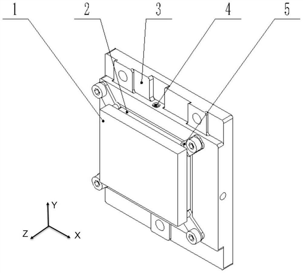
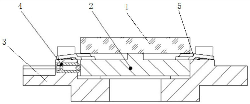
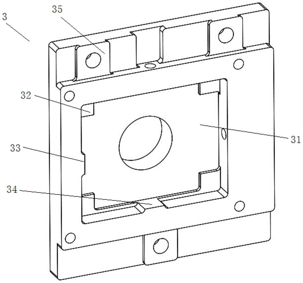
The invention discloses a low-temperature and high-stability support structure for reflective grating installation, comprising a grating pressing plate, a grating substrate, an elastic pressing sheet and a ball-head plunger; the back of the reflective grating is connected to the grating substrate by single-point bonding Fixed, the grating substrate is embedded in the installation groove of the grating pressure plate, and the positioning of the grating substrate in the X and Y directions is realized by the ball-head plungers arranged in the groove walls on both sides of the installation groove; the elastic pressure plate provides Z to the grating substrate Under the action of the elastic pressure plate and the installation reference surface of the bottom of the installation groove, the positioning of the grating substrate in the Z direction is realized. The support structure effectively isolates the reflection grating from the grating pressure plate structure while ensuring the support accuracy. The deformation under the action of temperature load is absorbed and buffered by the flexible structure, and the reflection grating is hardly subjected to the force that changes with temperature, effectively guaranteeing The surface shape accuracy of the grating is improved, and the temperature stability of the system is realized.

Description

Technical field [0001] The present invention is an optical engineering field, which involves a support structure, which specifically involves a low -temperature and high stability support structure for reflected grating installation. Background technique [0002] In the field of optical engineering, the optical machine system, especially the infrared light machine system, is very sensitive to the environmental state. In order to reduce the effects of heat background radiation on the system, the overall cooling of the entire infrared light machine system is required , Ensure the temperature stability of the optical system. Due to the influence of the ambient temperature of the low -temperature light machine system, structural components and optical components will cause squeezing deformation due to the non -matching coefficient between the connected components, which causes thermal stress, resulting in a rigid displacement of optical components, changes in optical surface surface ...

Claims


Application Information

Patent Timeline
Patent Type & Authority Patents(China)
IPC IPC(8): G02B7/00
CPCG02B7/00G02B7/008
Inventor 冯玉涛吴阳武俊强孙剑张兆会韩斌郝雄波
Owner XI'AN INST OF OPTICS & FINE MECHANICS - CHINESE ACAD OF SCI
Why Eureka
Try Eureka