Automatic precise milling machine machining and feeding and discharging device

A milling machine processing and precise technology, applied in positioning devices, milling machine equipment, metal processing and other directions, can solve the problems of position deviation, unstable grasping by the manipulator, inconvenient wheel processing and production, etc., and achieve the effect of reducing position deviation.

Pending Publication Date: 2021-12-14
佛山市南海飞越压铸制造有限公司
View PDF0 Cites 2 Cited by
  • Summary
  • Abstract
  • Description
  • Claims
  • Application Information

AI Technical Summary

Problems solved by technology

[0004] In view of the above-mentioned related technologies, the inventor believes that there is a defect in that: due to the slight vibration on the surface of the conveyor belt during transportation, when the hub is transported on the conveyor belt, there is still a certain gap between the baffles on both sides and the hub. Therefore, the position of the hub will in

Method used


Image

  • Automatic precise milling machine machining and feeding and discharging device
  • Automatic precise milling machine machining and feeding and discharging device
  • Automatic precise milling machine machining and feeding and discharging device

Examples


Embodiment 1

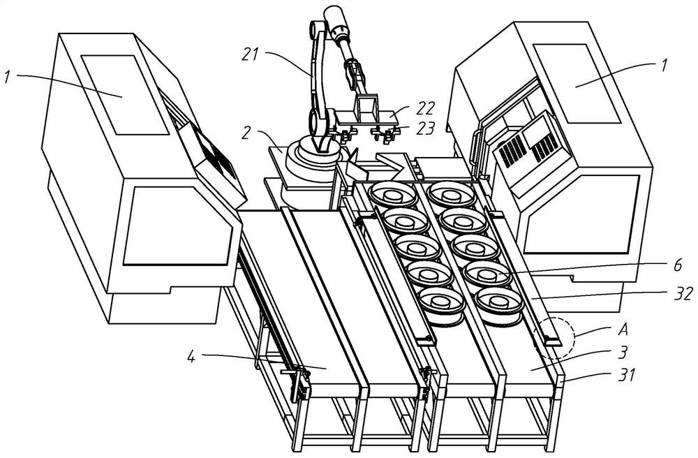
[0038] refer to figure 1 , an automatic precision milling machine processing and loading and unloading device, including a feeding conveyor belt 3 placed on the ground of the working environment and used to transport the hub 6. In this embodiment, the number of feeding conveyor belts 3 is two.

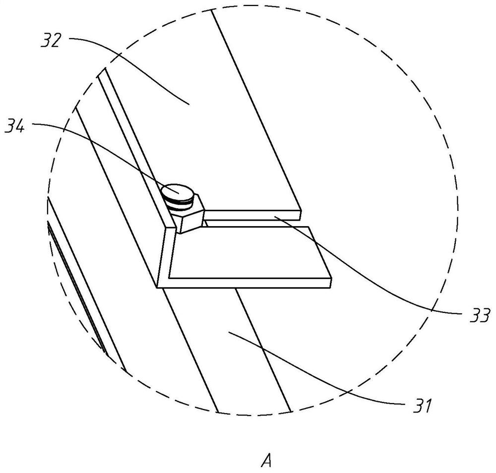
[0039] refer to figure 1 and figure 2 On both sides of the two feeding conveyor belts 3 and on the side near the output end of the feeding conveyor belt 3, baffles 31 are fixed, and an adjusting plate 32 is detachably connected to the top of the two side baffles 31, and the top of the adjusting plate 32 runs through. There is a strip hole 33 , the extension direction of the strip hole 33 is perpendicular to the conveying direction of the feeding conveyor belt 3 , and one end of the strip hole 33 communicates with the side wall of the regulating plate 32 . An adjusting bolt 34 is threaded on the strip hole 33, and the screw-in end of the adjusting bolt 34 is threaded with the baffle ...

Embodiment 2

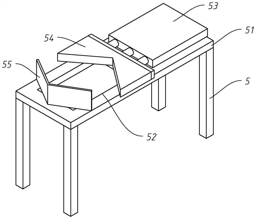
[0060] refer to Figure 4 , Different from Embodiment 1, in this embodiment, the first positioning block 54 and the second positioning block 55 are provided with arc-shaped slopes on opposite surfaces, and the openings of the two arc-shaped slopes are opposite to each other.

[0061] The implementation principle of an automatic precision milling machine processing and loading and unloading device in the embodiment of the present invention is as follows:

[0062] When the wheel hub 6 to be processed is transferred from the feeding conveyor belt 3 to the top plate 51 between the first positioning block 54 and the second positioning block 55, the hydraulic cylinder 53 is activated to make the piston rod push the first positioning block 54, so that the wheel hub 6 is in the The first positioning block 54 moves toward the second positioning block 55 under the clamping of the arc-shaped slope at the end, until the hub 6 is sandwiched between the arc-shaped slopes of the second posit...


PUM


Abstract

The invention discloses an automatic precise milling machine machining and feeding and discharging device, and belongs to the technical field of machining equipment. The automatic precise milling machine machining and feeding and discharging device comprises a feeding and discharging device used for conveying hubs, and a grabbing device arranged on the feeding and discharging side and used for grabbing the hubs on the feeding and discharging device; and a positioning device used for positioning the hubs is arranged on one side of the feeding and discharging device. According to the automatic precise milling machine machining and feeding and discharging device, the hubs can be repositioned through the positioning device additionally arranged on one side of the feeding and discharging device, accordingly, the position deviation of the hubs on a mechanical arm is reduced, and accordingly the situation that the positions of the hubs and a milling machine clamp deviate or the hubs fall off from the mechanical arm is reduced.

Description

technical field [0001] The invention relates to the field of processing equipment, in particular to an automatic precision milling machine processing and loading and unloading device. Background technique [0002] In the processing process of the wheel hub, it is necessary to use a milling machine to further process the wheel hub. In order to improve the processing efficiency of the wheel hub, the conveyor belt is usually used to transport the hub at present, and the robot arm automatically grabs the wheel hub to be processed on the conveyor belt, and finally the robot arm grabs the wheel hub The taken hub is put into the milling machine to complete the loading. [0003] Since the manipulator can generally only grab at a fixed position according to a predetermined program, it is necessary to install baffles on both sides of the conveyor belt to limit the hub on the conveyor belt to reduce the lateral position deviation of the hub. However, in the actual processing process, ...

Claims


Application Information

Patent Timeline
IPC IPC(8): B23Q7/00B23Q7/04B23Q3/18B23C3/00
CPCB23Q7/003B23Q7/04B23Q3/18B23C3/00
Inventor 杨伟炫李根贵杨开祥张维国
Owner 佛山市南海飞越压铸制造有限公司
Why Eureka
Try Eureka