
In Situ Cryogenic Transmission Electron Microscopy Sample Holder for High-Frequency Signal Transmission

An electron microscope and in-situ low-temperature technology, which is applied to circuits, discharge tubes, electrical components, etc., can solve problems such as the inability of wires to conduct signals accurately, and achieve the effect of low-loss transmission

Active Publication Date: 2020-12-22
FUDAN UNIV
View PDF8 Cites 0 Cited by
  • Summary
  • Abstract
  • Description
  • Claims
  • Application Information

AI Technical Summary

Problems solved by technology

When the frequency of the signal gradually rises to the GHz level, ordinary wires cannot conduct the signal accurately, but a coaxial cable with shielding ability must be used

Method used


Image

  • In Situ Cryogenic Transmission Electron Microscopy Sample Holder for High-Frequency Signal Transmission
  • In Situ Cryogenic Transmission Electron Microscopy Sample Holder for High-Frequency Signal Transmission
  • In Situ Cryogenic Transmission Electron Microscopy Sample Holder for High-Frequency Signal Transmission

Examples


Embodiment Construction

[0030] In order to make the technical solutions, objectives and advantages of the embodiments of the present invention clearer, specific embodiments of the present invention will be described in detail below in conjunction with the accompanying drawings.

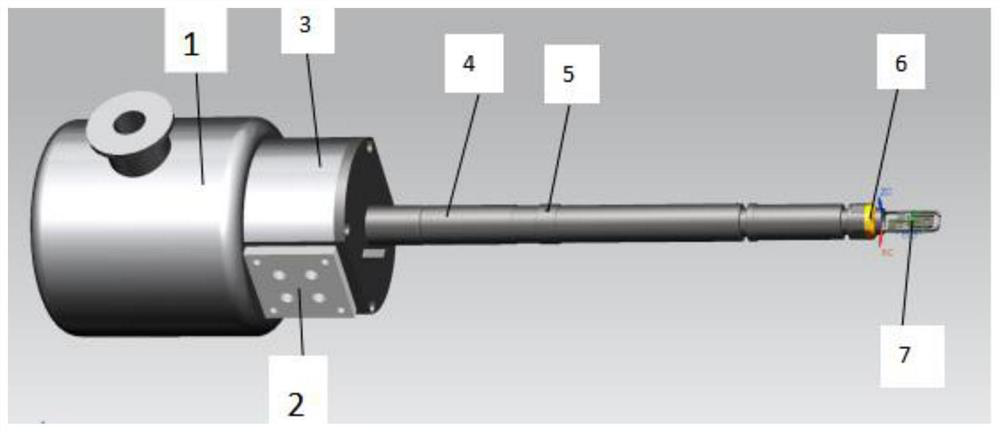
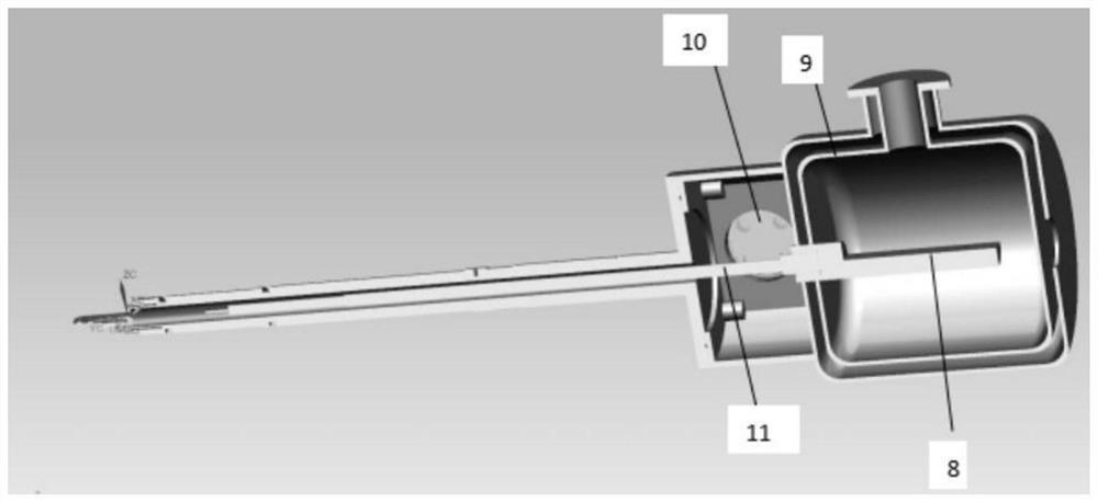
[0031] A low-temperature radio frequency transmission electron microscope sample rod, comprising: Dewar outer tank 1, plastic flange 2, transition chamber 3, sample rod shell 4, guide pin 5, sealing ring 6, sample rod head 7, heat conduction copper column 8 , Dewar tank inner tank 9, ordinary flange 10, sample rod inner rod 11, flexible resistor (not shown in the figure), temperature sensor (not shown in the figure), copper wire (not shown in the figure).

[0032] The Dewar outer tank 1 is welded to the top of the Dewar inner tank 9, and a small hole is left at the end of the Dewar outer tank 1 for connecting with a vacuum system, and it is close to the transition chamber 3 for vacuuming before use. The inner tank 9 of the e...


PUM


Abstract

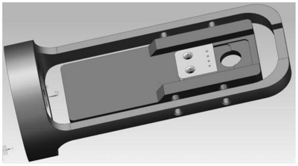
The invention belongs to the technical field of transmission electron microscopes and in particular relates to an in situ low temperature transmission electron microscope sample holder applicable to high frequency signal transmission. The in situ low temperature transmission electron microscope sample holder comprises a welded insulated cylinder, a transition bin, a sample holder, a sample holderhead and a coaxial cable; the coaxial cable adopts four coaxial conductors, is led out from a gap between an oxygen-free copper inner core and an outer rod and is led to the outside by virtue of a flange and a vacuum joint, and low-loss transmission of a 0-4GHz high frequency signal is realized; a heating resistor slice is designed at the front end of the inner core, a temperature sensor is designed near a fixed sample, and closed-loop control on temperature of a sample is formed by virtue of an externally connected temperature controller; the welded insulated cylinder at the tail end is designed into a horizontal cylinder shape, and influence on position accuracy as center of gravity is changed when the sample holder rotates can be reduced. The in situ low temperature transmission electron microscope sample holder provided by the invention realizes continuous temperature changing regulation from 100 K to 300 K, supports introduction of a high frequency electric signal, realizes in situ regulation on a temperature field, an electric field and a magnetic field of a sample by cooperating with a transmission electron microscope and achieves multi-field coupled in situ testing.

Description

technical field [0001] The invention belongs to the technical field of transmission electron microscopy, in particular to an in-situ transmission electron microscope sample rod. Background technique [0002] With the gradual development of transmission electron microscope technology, there are more and more demands for in-situ testing, and the development of the electron microscope itself and the sample holder has become one of the important development directions. In recent years, the development of in-situ technology has realized the testing of samples in liquid, gas, light, magnetic field, deformation, electric field, etc. Wait for a more in-depth analysis. However, there are still some techniques to be improved. [0003] In the field of spintronics, it is a very important physical process to use current to drive the reversal of the magnetic moment. The analysis of this process is of great significance in the development of future magnetoelectric storage devices. Howev...

Claims


Application Information

Patent Timeline
Patent Type & Authority Patents(China)
IPC IPC(8): H01J37/20H01J37/26
Inventor 车仁超曾庆文赵雪冰张捷
Owner FUDAN UNIV
Learn More