[0033] The present invention will be further described below in conjunction with the drawings and specific embodiments of the specification.
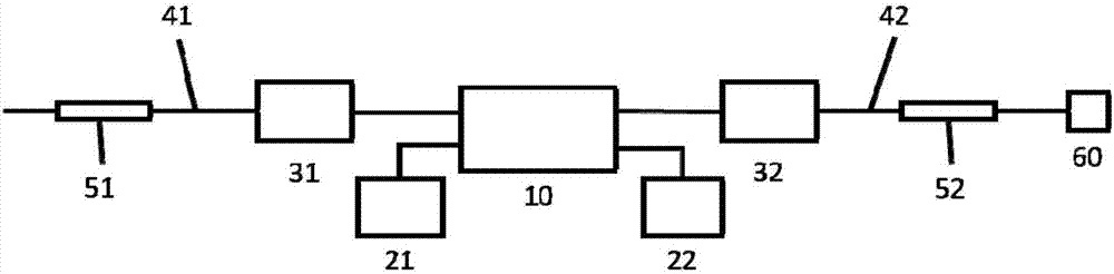
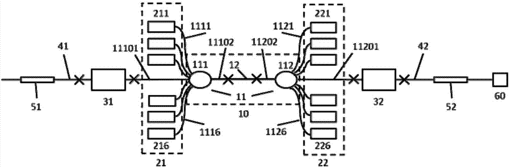
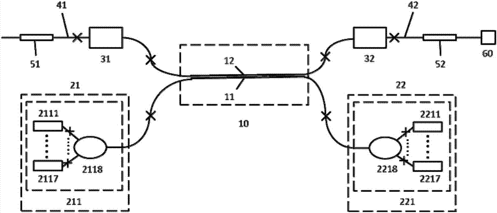
[0034] Such as figure 1 As shown, the present invention consists of a gain module 10, a first pump module 21, a second pump module 22, a first fiber mode field adapter 31, a second fiber mode field adapter 32, a first photosensitive fiber 41, a first fiber grating 51. The second photosensitive fiber 42, the second fiber grating 52 and the output coupling end 60 are composed. The first pump module 21 and the second pump module 22 are respectively connected to the pump light input end of the gain module 10. The input ends of the first optical fiber mode field adaptor 31 and the second optical fiber mode field adaptor 32 are respectively connected to the signal light output end of the gain module 10. The output end of the first optical fiber mode field adapter 31 is connected to the input end of the first photosensitive optical fiber 41. The output end of the second optical fiber mode field adapter 32 is connected to the input end of the second photosensitive optical fiber 42. A first fiber grating 51 is written in the core of the first photosensitive optical fiber 41, and a second fiber grating 52 is written in the core of the second photosensitive optical fiber 42. The input end of the output coupling end 60 is connected to the output end of the second photosensitive optical fiber 42.
[0035] The gain module 10 of the present invention is composed of a pump coupling module 11 and a double-clad ytterbium-doped fiber 12. The pump light passes through the pump coupling module 11 and is coupled from the side of the inner cladding of the double-clad ytterbium-doped fiber 12 to the double-clad doped fiber. In the ytterbium fiber 12, the ytterbium ions in the core of the double-clad ytterbium-doped fiber 12 are pumped to generate a light field in the 980nm band. The core-cladding diameter ratio (ie, the core diameter divided by the inner cladding diameter) of the double-clad ytterbium-doped fiber 12 should be greater than or equal to 30%.
[0036] The pump coupling module 11 can adopt two technical solutions. The technical solution is the same figure 2 As shown, the pump coupling module 11 is composed of a first side pump combiner 111 and a second side pump combiner 112. The first side pump combiner 111 and the second side pump combiner 112 The beamer 112 is an optical fiber device that couples the pump light to the inner cladding of the double-clad fiber via the inner cladding side of the double-clad fiber, and includes no less than 1 pump light input end and 1 signal light input. The number of pump light input ends of the first side pump beam combiner 111 and the second side pump beam combiner 112 may be equal or different. The signal light input terminal 11101 of the first side pump beam combiner 111 and the signal light input terminal 11201 of the second side pump beam combiner 112 are the two signal light input terminals of the pump coupling module 11; The output end 11102 of the side pump beam combiner 111 and the output end 11202 of the second side pump beam combiner 112 are the two output ends of the pump coupling module 11; the first side pump beam combiner 111 The pump light input terminal (1111-111N) ( figure 2 Where N is 6, N is the number of pump light input ends of the first side pump beam combiner 111) and the pump light input ends (1121-112M) of the second side pump beam combiner 112 ( figure 2 Where M is 6, and M is the number of pump light input ends of the second side pump beam combiner 112), which is the pump light input end of the pump coupling module 11 (N+M in total). The output end 11102 of the first side pumping combiner 111 and the output end 11202 of the second side pumping combiner 112 are connected to both ends of the double-clad ytterbium-doped fiber 12, and the pump coupling module 11 The optical input ends are the pump light input ends of the gain module 10 (N+M in total), and the two signal light input ends of the pump coupling module 11 are the two signal light output ends of the gain module 10.
[0037] The pump coupling module 11 can also be used such as image 3 The second technical solution shown is to use K multimode fibers so that the cores of the K multimode fibers are in optical contact with the inner cladding of the double-clad ytterbium-doped fiber 12 (K should be less than or equal to [π(1+R 1 /r 1 )], where R 1 Is the inner cladding diameter of double-clad ytterbium-doped fiber 12, r 1 Is the minimum core diameter of the multimode fiber), so that the pump light transmitted in the K multimode fibers of the pump coupling module 11 can be coupled to the double-clad ytterbium-doped fiber through optical contact methods such as evanescent wave coupling In the 12 inner cladding, the ytterbium ions in the 12 core of the double-clad ytterbium-doped fiber are thus pumped to produce a light field in the 980nm band. In this scheme, the two ends of the K multimode fibers of the pump coupling module 11 are the pump light input ends of the gain module 10 (2K in total), and the two ends of the double-clad ytterbium-doped fiber 12 are the gain modules. 10 2 signal light output terminals.
[0038] The first pump module 21 of the present invention includes multiple pump sub-modules, and the number of pump sub-modules should be less than or equal to N (when the pump coupling module 11 adopts the first scheme) or K (when the pump coupling module 11 adopts the In the second scheme), the number of pump light input ends of the first scheme of the pump coupling module 11 is (N+M), and the number of pump light input ends of the second scheme is 2K. The pump sub-module can choose a pigtail to output a semiconductor laser in the 900nm~960nm band (such as figure 2 The pump sub-module 211-216 in the first embodiment shown), at this time, the pigtail of the semiconductor laser is the output fiber of the pump sub-module; a well-known bundle structure can also be used, that is, multiple pigtails output 900nm The pigtailed output semiconductor laser in the ~960nm band is combined into an output fiber (that is, the output fiber of the pump submodule) through at least one fiber pump combiner (such as image 3 The pump sub-module 211 in the second embodiment shown). The output fibers of all pump sub-modules constituting the first pump module 21 are the output fibers of the first pump module 21. The output fiber of the first pump module 21 is connected to the input fiber of the pump light input end fiber of the gain module 10 (if the pump coupling module 11 adopts the first solution, the output fiber of the first pump module 21 is connected to the N of the gain module 10 If the pump coupling module 11 adopts the second solution, the output fibers of the first pump module 21 are connected to the K pump light input fibers of the gain module 10). The diameter of the output fiber of the first pump module 21 should be less than or equal to the diameter of the fiber at the pump light input end of the gain module 10; the numerical aperture of the output fiber of the first pump module 21 should be less than or equal to the fiber at the pump light input end of the gain module 10 The numerical aperture.
[0039] The second pump module 22 of the present invention includes multiple pump sub-modules, and the number of pump sub-modules should be less than or equal to M (when the pump coupling module 11 adopts the first scheme) or K (when the pump coupling module 11 adopts the The second option). Each pump sub-module is composed of a semiconductor laser with a pigtail output in the 900nm-960nm band. The pump sub-module can choose a pigtail to output a semiconductor laser in the 900nm~960nm band (such as figure 2 The pump sub-modules 221-226 in the first embodiment shown), at this time, the pigtail of the semiconductor laser is the output fiber of the pump sub-module; a well-known bundle structure can also be used, that is, multiple pigtails output 900nm The pigtail output semiconductor laser in the ~960nm band is combined into an output fiber (that is, the output fiber of the pump sub-module) through at least one fiber pump combiner (such as image 3 The second pump sub-module 221 in the second embodiment shown). The output fibers of all pump sub-modules constituting the second pump module 22 are the output fibers of the second pump module 22. The output fiber of the second pump module 22 is connected to the pump light input end fiber of the gain module 10 (if the pump coupling module 11 adopts the first scheme, the output fiber of the second pump module 22 is connected to the other M pumps of the gain module 10). If the pump coupling module 11 adopts the second solution, the output fiber of the second pump module 22 is connected to the other K pump light input fibers of the gain module 10). The diameter of the output fiber of the second pump module 22 should be less than or equal to the diameter of the fiber at the input end of the pump light of the gain module 10; the numerical aperture of the output fiber of the second pump module 22 should be less than or equal to the fiber at the input end of the pump light of the gain module 10 The numerical aperture.
[0040] The input end of the first fiber mode field adaptor 31 is connected to the signal light output end of the gain module 10, and the diameter of the fiber core at the input end of the first fiber mode field adaptor 31 is required to be equal to the diameter of the fiber core at the signal light output end of the gain module 10 ; The output end of the first optical fiber mode field adapter 31 is connected to the input end of the first photosensitive optical fiber 41, and the diameter of the fiber core at the output end of the first optical fiber mode field adapter 31 is required to be equal to the diameter of the input end of the first photosensitive optical fiber 41. The first optical fiber mode field adaptor 31 can adopt an optical fiber mode field adaptor, or Q 1 A series structure of sub-fiber mode field adapters (that is, the output end of the i-th sub-fiber mode field adaptor is connected to the input end of the i+1 sub-fiber mode field adaptor, and the core diameter of the output end of the i-th sub-fiber mode field adaptor is required to be The core diameters of the input end of the i+1th sub-fiber mode field adapter are equal, i=1, 2, ..., Q 1 -1, Q 1 Is a natural number, the input end of the first optical fiber mode field adapter is the input end of the first optical fiber mode field adapter 31, and the Q-th 1 The output end of the sub-fiber mode field adapter is the output end of the first optical fiber mode field adapter 31, Q 1 Should be less than or equal to 10, preferably less than or equal to 5).
[0041] The input end of the second fiber mode field adapter 32 is connected to the signal light output end of the gain module 10, and the diameter of the fiber core at the input end of the second fiber mode field adapter 32 is required to be equal to the diameter of the fiber core at the signal light output end of the gain module 10 The output end of the second optical fiber mode field adapter 32 is connected to the input end of the second photosensitive optical fiber 42, and the diameter of the fiber core at the output end of the second optical fiber mode field adapter 32 is required to be equal to the diameter of the input end of the second photosensitive optical fiber 42. The second optical fiber mode field adaptor 32 can be used in combination with the needs, and a single optical fiber mode field adaptor can also be used. 2 Sub-fiber mode field adapter series structure (Q 2 Is a natural number, Q 2 Can be used with Q 1 Equal or unequal, Q 2 Should be less than or equal to 10, preferably less than or equal to 5).
[0042] The center wavelength of the first fiber grating 51 written in the first photosensitive fiber 41 should be in the laser wavelength band, namely: 970nm-985nm, the reflectance at the center wavelength should be greater than or equal to 90%, and the sidelobe suppression ratio should be greater than or equal to 20dB. The output end of the first photosensitive optical fiber 41 should suppress the reflection of the optical field from the end face of the optical fiber, and the common oblique cutting can be adopted but not limited to.
[0043] The center wavelength of the second fiber grating 52 written in the second photosensitive fiber 42 should be approximately equal to the first fiber grating 51 (the deviation should be less than 1 nm), and the reflectivity at the center wavelength should be greater than or equal to 10%, and the side lobe suppression ratio should be Greater than or equal to 25dB.
[0044] The input end of the output coupling end 60 is connected to the output end of the second photosensitive fiber 42, and the input end fiber of the output coupling end 60 should have the same diameter as the output end of the second photosensitive fiber 42. The structure can adopt but is not limited to bevel cutting of the end face of the optical fiber or end cap.
[0045] figure 2 The first embodiment of the present invention is given. The double-clad ytterbium-doped fiber 12 selected by the gain module 10 of this embodiment has a core-clad diameter ratio of 30%; the pump coupling module 11 adopts the first technical scheme, that is, two lateral sides with 6 pump light input ends are selected. Pump beam combiner (ie N=M=6). The first pump module 21 includes 6 pump sub-modules 211-216, and each pump sub-module is composed of a pigtailed semiconductor laser. The second pump module 22 also includes six pump sub-modules 221-226, and each pump sub-module is composed of a pigtailed semiconductor laser. The first optical fiber mode field adaptor 31 and the second optical fiber mode field adaptor 32 have the same structure, and both are composed of two sub optical fiber mode field adaptors connected in series (ie Q 1 =Q 2 = 2). The following takes the first optical fiber mode field adapter 31 as an example to introduce the structure of the optical fiber mode field adapter, such as Figure 4 As shown, the first fiber mode field adapter 31 is composed of a first sub fiber mode field adapter 311 and a second sub fiber mode field adapter 312; the output end of the first sub fiber mode field adapter 311 and the second sub fiber mode field adapter 312 The input terminal is connected. The first photosensitive fiber 41 and the second photosensitive fiber 42 have the same structure. The center wavelength of the first fiber grating 51 is 978nm, the reflectivity of the center wavelength is 90%, and the sidelobe suppression ratio is 20dB; the center wavelength of the second fiber grating 52 is 977.9nm, the reflectivity of the center wavelength is 25%, and the side lobe suppression ratio is 45dB. The output end of the second photosensitive optical fiber 42 is cut at an oblique angle as the output coupling end 60. Embodiment 1 Under the condition that both pump module 21 and pump module 22 can provide 900W pump light, the output laser power in the 980nm band can reach 990W, the optical-to-optical conversion efficiency is 55%, and the electro-optical conversion efficiency can reach 25%. .
[0046] image 3 The second embodiment of the present invention is given. The core-cladding diameter ratio of the double-clad ytterbium-doped fiber selected for the gain module 10 of this embodiment is 50%; the pump coupling module 11 adopts the second technical solution, that is, a multimode fiber (K=1) is used, and the The cladding ytterbium-doped fiber 12 constitutes a side-pumped ytterbium-doped fiber. The first pump module 21 includes a pump sub-module 211. The pump sub-module consists of seven pigtailed semiconductor lasers 2111-2117 pumped by a 7×1 fiber The beam combiner 2118 combines beam structure. The second pump module 22 includes a pump sub-module 221, which is composed of seven pigtailed semiconductor lasers 2211-2217 through a 7×1 fiber combiner 2218. Both the first pump module 21 and the second pump module 22 can provide 700W pump light. The first optical fiber mode field adapter 31 and the second optical fiber mode field adapter 32 have the same structure. The first photosensitive fiber 41 and the second photosensitive fiber 42 have the same structure. The center wavelength of the first fiber grating 51 is 977nm, the reflectivity of the center wavelength is 98%, and the sidelobe suppression ratio is 25dB; the center wavelength of the second fiber grating 52 is 977nm, the reflectivity of the center wavelength is 10%, and the sidelobe suppression ratio is 25dB. The output end of the second photosensitive optical fiber 42 is cut at an oblique angle as the output coupling end 60. In the second embodiment, if both the first pump module 21 and the second pump module 22 can provide 700W pump light, the output laser power in the 980nm band can reach 812W, the optical-to-optical conversion efficiency is 58%, and the electro-optical conversion efficiency can be Reach 25%.