Low-temperature high-stability supporting structure for installing reflective optical grating

A technology with high stability and support structure, which is applied in the field of optical engineering, can solve problems such as the inability to control the surface shape of optical elements well, the complex support structure at low temperature, and the impact on system performance, etc., to achieve temperature stability, simple structure, and easy assembly The effect of low process requirements

Active Publication Date: 2021-12-10
XI'AN INST OF OPTICS & FINE MECHANICS - CHINESE ACAD OF SCI
View PDF8 Cites 0 Cited by
  • Summary
  • Abstract
  • Description
  • Claims
  • Application Information

AI Technical Summary

Problems solved by technology

[0005] In order to solve the problem that most of the low-temperature support structures of reflective gratings for low-temperature environments are relatively complex and cannot well control the surface shape changes of optical elements, which will cause the system interference fringes to be inclined and bent, and the modulation degree will be reduced, which will affect the system performance. The present invention provides A low-temperature high-stability support structure for reflective grating installation

Method used


Image

  • Low-temperature high-stability supporting structure for installing reflective optical grating
  • Low-temperature high-stability supporting structure for installing reflective optical grating
  • Low-temperature high-stability supporting structure for installing reflective optical grating

Examples


Embodiment Construction

[0040] In order to make the above-mentioned purposes, features and advantages of the present invention more obvious and easy to understand, the specific implementation modes of the present invention will be described in detail below in conjunction with the accompanying drawings. Obviously, the described embodiments are part of the embodiments of the present invention, not all of them. Example. Based on the embodiments of the present invention, all other embodiments obtained by ordinary persons in the art without creative efforts shall fall within the protection scope of the present invention.

[0041] In the following description, a lot of specific details are set forth in order to fully understand the present invention, but the present invention can also be implemented in other ways different from those described here, and those skilled in the art can do it without departing from the meaning of the present invention. By analogy, the present invention is therefore not limited ...


PUM

PropertyMeasurementUnit
Parallelismaaaaaaaaaa

Abstract

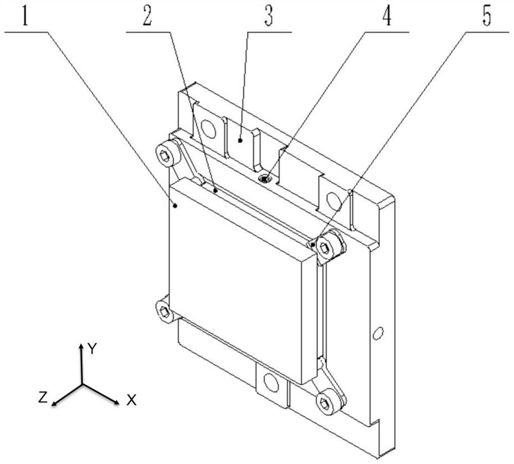
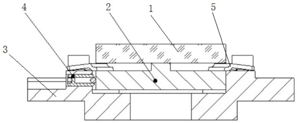
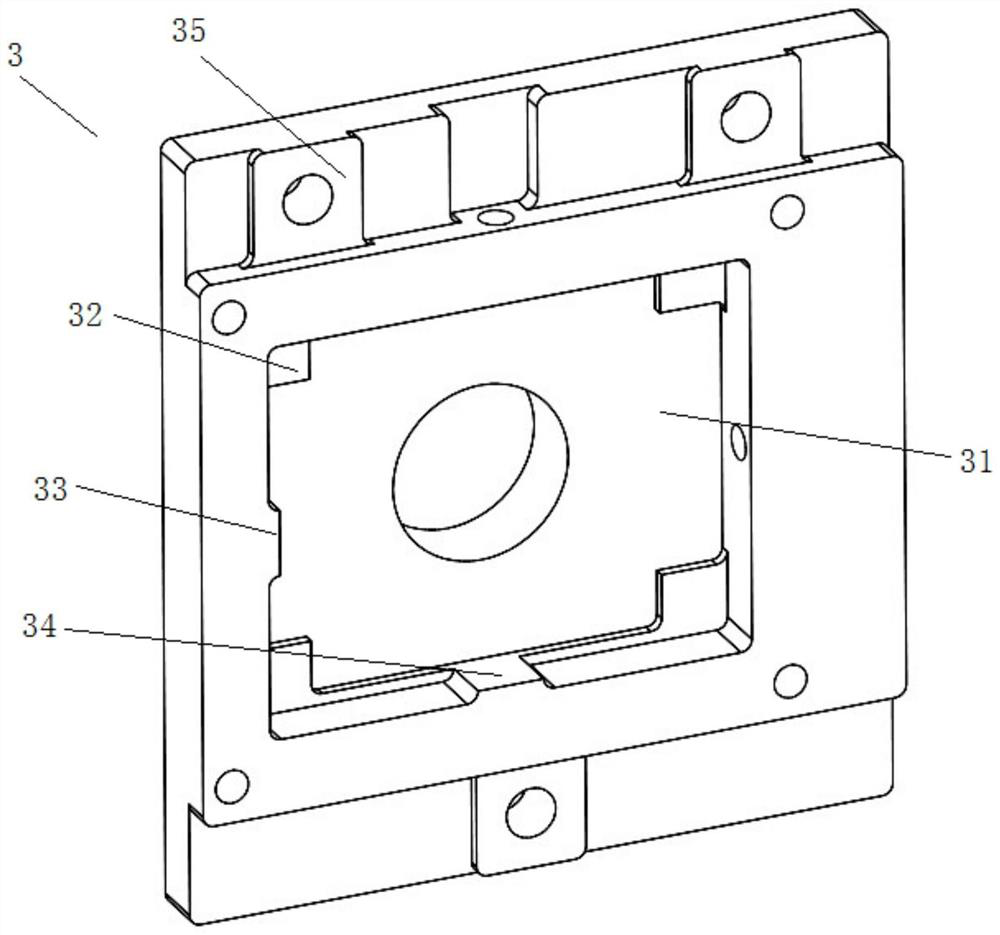
The invention discloses a low-temperature high-stability supporting structure for installing a reflective optical grating. The low-temperature high-stability supporting structure comprises an optical grating pressing plate, an optical grating substrate, an elastic pressing piece and a ball plunger; the back of the reflective optical grating is fixed with the optical grating substrate in a single-point bonding mode, the optical grating substrate is embedded in the mounting groove of the optical grating pressing plate, and positioning of the optical grating substrate in the X direction and the Y direction is achieved through ball plungers arranged in the groove walls of the two sides of the mounting groove; Z-direction pre-tightening force is provided for the optical grating substrate through the elastic pressing plate, and positioning of the optical grating substrate in the Z direction is achieved under the action of the elastic pressing plate and the installation datum plane of the groove bottom of the installation groove. According to the supporting structure, the reflection optical grating and the optical grating pressing plate structure are effectively isolated while the supporting precision is guaranteed, deformation under the temperature load effect is absorbed and buffered by a flexible structure, the reflection optical grating is hardly subjected to acting force changing along with the temperature, the surface shape precision of the grating surface is effectively guaranteed, and the temperature stability of a system is achieved.

Description

technical field [0001] The invention belongs to the field of optical engineering and relates to a supporting structure, in particular to a low-temperature and high-stability supporting structure used for installation of reflective gratings. Background technique [0002] In the field of optical engineering, optical-mechanical systems, especially infrared optical-mechanical systems, are very sensitive to environmental conditions. In order to reduce the impact of thermal background radiation on the system, it is usually necessary to cool down the entire infrared optical-mechanical system and perform radiation suppression and heat insulation treatments. , to ensure the temperature stability of the optical system. Due to the impact of violent fluctuations in the ambient temperature of the low-temperature optomechanical system, the structural components and optical components will be squeezed and deformed due to the mismatch of thermal expansion coefficients between the connecting...

Claims


Application Information

Patent Timeline
IPC IPC(8): G02B7/00
CPCG02B7/00G02B7/008
Inventor 冯玉涛吴阳武俊强孙剑张兆会韩斌郝雄波
Owner XI'AN INST OF OPTICS & FINE MECHANICS - CHINESE ACAD OF SCI
Why Eureka
Try Eureka