Method for manufacturing pre-cut SDB FinFET

A manufacturing method and oxide layer technology, applied in semiconductor/solid-state device manufacturing, electrical components, circuits, etc., can solve problems such as device performance degradation, and achieve the effects of reduced pressure release risk and good filling ability

Pending Publication Date: 2021-12-10
SHANGHAI HUALI INTEGRATED CIRCUTE MFG CO LTD
View PDF0 Cites 0 Cited by
  • Summary
  • Abstract
  • Description
  • Claims
  • Application Information

AI Technical Summary

Problems solved by technology

[0006] In view of the above-mentioned shortcomings of the prior art, the purpose of the present invention is to provide a method for manufacturing SDB FinFET first, which is used to solve the problem that the p

Method used


Image

  • Method for manufacturing pre-cut SDB FinFET
  • Method for manufacturing pre-cut SDB FinFET
  • Method for manufacturing pre-cut SDB FinFET

Examples


Example Embodiment

[0064] The embodiments of the present invention will be described below with reference to the specific examples of the present invention, and those skilled in the art can easily understand other advantages and efficacy of the present invention. The present invention can also be implemented or applied by other embodiments, and various details in this specification may also be based on different viewpoints and applications without departing from the spirit of the invention.

[0065] Please refer to Figure 2 to Figure 17 . It should be noted that the illustrations provided in the present embodiment will only illustrate the basic contemplation of the present invention, and only the components, shapes, shapes, and in accordance with the components of the present invention are shown in the schematic manner. Dimensions, the type, number, and proportion of each component can be a random change in the actual implementation of the actual implementation, and its component layout may be more ...


PUM


Abstract

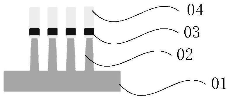
The invention provides a method for manufacturing a pre-cut SDB FinFET. The method comprises the steps of: forming a plurality of Fin structures which are arranged at intervals in the longitudinal direction on a substrate, and forming SiN layers on the Fin structures; depositing thin oxide layers; performing annealing after depositing a dielectric layer; grinding to expose the upper surfaces of the SiN layers; forming SDB photoresist patterns on the SiN layers; etching the SiN layers and the Fin structures along the SDB photoresist patterns to form SDB grooves; forming oxide layers at the bottoms of the SDB grooves; forming siN in the middles of the SDB grooves; forming SiC on the tops of the SDB grooves; removing the SiN layers to expose the upper surfaces of the Fin structures, and exposing the SiC; forming a plurality of dummy gates arranged at intervals in the transverse direction on the Fin structures and the SDB grooves; forming SiP epitaxial structures on the Fin structures between the two adjacent dummy gates on one side of each SDB groove; forming SiGe epitaxial structures on the Fin structures between two adjacent dummy gates on the other sides of the SDB grooves; depositing interlayer dielectric layers to cover the dummy gates; grinding the interlayer dielectric layers until the tops of the dummy gates are exposed; removing the dummy gates to form grooves; and forming HK metal gates.

Description

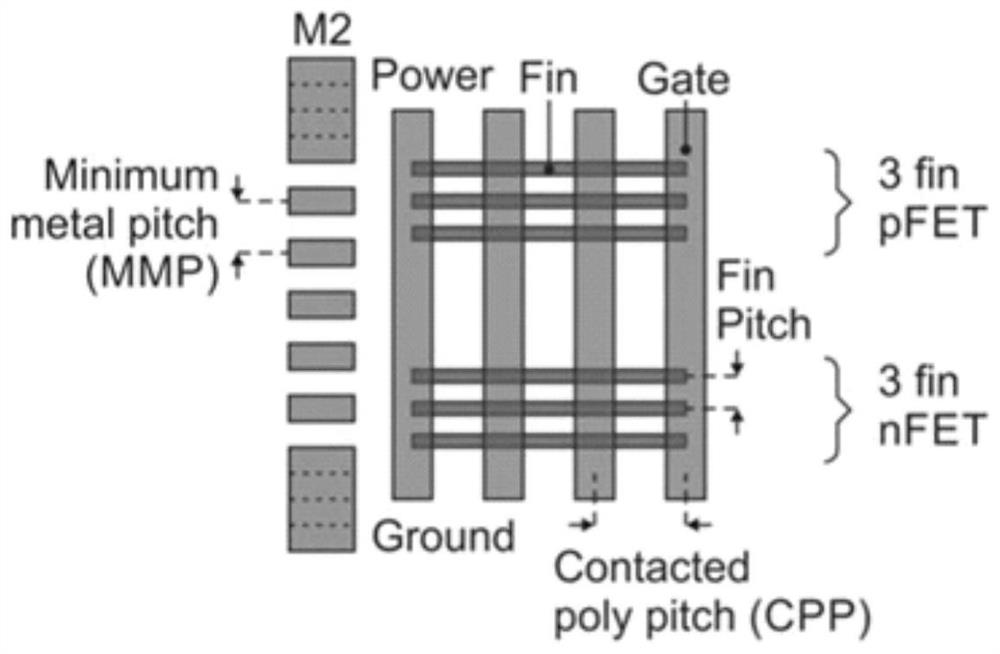
technical field [0001] The invention relates to the technical field of semiconductors, in particular to a method for manufacturing a first-cut SDB FinFET. Background technique [0002] Logic designs in standard cells are created using standard cells. The height of the cell is the number of tracks multiplied by the metal pitch (Pitch), and the track and Pitch are measured with metal layer 2 (M2). figure 1 Shown as a schematic diagram of a 7.5 rail unit, half of the height of the power supply (Power) and the ground rail (Ground) are located in the upper unit and the lower unit, respectively. [0003] The cell width is related to the contact poly pitch (CPP), and the number of CPPs that make up the cell width depends on the cell type and whether the cell has a double diffusion break (DDB) or a single diffusion break (SDB). [0004] A DDB adds one and a half CPPs on each side of the cell. For actual cells, such as NAND gates and cell scan flip-flops, the number of CPPs on the...

Claims


Application Information

Patent Timeline
IPC IPC(8): H01L21/336H01L29/16
CPCH01L29/66795H01L29/1608
Inventor 李勇
Owner SHANGHAI HUALI INTEGRATED CIRCUTE MFG CO LTD
Why Eureka
Try Eureka