Adjustable electromagnetic array element and intelligent surface
A control element and electromagnetic technology, applied in electrical components, circuits, antenna arrays, etc., can solve the problems of poor performance of RIS solutions, inability of RIS to meet multi-bit multi-polarization performance requirements, high manufacturing costs and manufacturing difficulties, and improve reliability. performance, break through performance limitations, and improve stability
- Summary
- Abstract
- Description
- Claims
- Application Information
AI Technical Summary
Problems solved by technology
Method used
Image

Examples
Example
[0115] Example
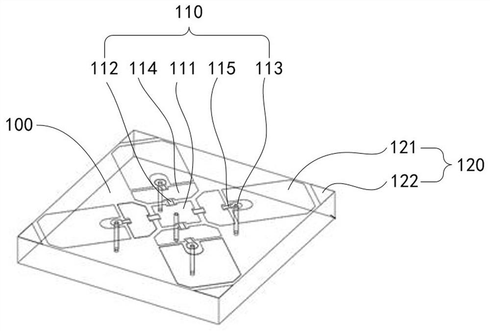
[0116] Refer Figures 1 to 7 Examples give a 4.9 GHz dynamic 2 + 2 (2bit + bipolarized) reflective RIS1000 specific embodiment (hereinafter referred to herein). Refer Image 6 and Figure 7 ,in, Image 6 10 × 10 conventional super surface 2000 (related technology super surface), Figure 7 A 10 × 10 parasitic hypermation 1000 provided in this example. It can be seen that the parasitic super surface 1000 is constituted in a conventional super-surface 2000 to load the parasitic unit 120. The parasitic super surface 1000 includes 10 × 10 electromagnetic matrix elements 1100.
[0117] The electromagnetic matrix elevational 1100 of this example includes two portions, that is, the reflective portion of the microstrip structure and the bias portion of the stripline structure.
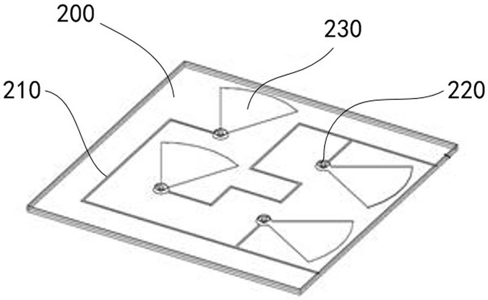
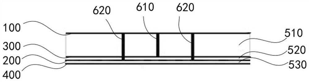
[0118] The reflective portion includes the reflective circuit layer 100, the first dielectric plate 510, the first floor layer 300, and the bias portion includes the first floor layer 300, the second di...
Example
[0136] Example 2
[0137] Example 2 gives a strip-shaped single-polarized dynamic 2 + 1 (2bit + single-polarized) reflective RIS3000 specific embodiment, such as Figure 14 to 17 As shown, the electromagnetic array element of the present example is a single polarized electromagnetic matrix element 3100. Figure 16 and Figure 17 A schematic structural diagram of 10 × 10 unipolar 2 + 1 reflective RIS3000 in strip-shaped parasitic super surface is shown. The parasitic super surface includes 10 × 10 single-polarized electromagnetic matrix elements 3100.
[0138] The electromagnetic array element of this example is a single-polarized electromagnetic matrix element 3100, and the monolarized electromagnetic matrix element 3100 also includes a reflective portion and a bias portion. The reflected circuit layer as a reflective portion body includes a reflecting unit 110 and a parasitic unit 120). The reflecting unit 110 and the parasitic unit 120 are located on both sides of the dielectric pl...
Example
[0141] Example three
[0142] Example II showed a specific embodiment of a circularly polarized dynamic 2 Bit reflection RIS4000, such as Figure 18 and Figure 19 As shown, the electromagnetic matrix element of the present example is a circular polarized electromagnetic matrix element 4100. Figure 19 A schematic structural diagram of 10 × 10 circular polarization dynamic 2 Bit reflective RIS4000 based on a honeycomb parasitic super surface. The parasitic super surface includes 10 x 10 circular polarization electromagnetic matrix elements 4100.
[0143] The electromagnetic matrix elements of this example are circularly polarized electromagnetic matrix elements 4100, and the circularly electromagnetic matrix elevational 4100 also includes a reflective portion and a bias portion.
[0144] Refer Figure 18 The reflective circuit layer as a reflective portion body includes a reflecting unit 110 and a parasitic unit 120. The reflecting unit 110 and the parasitic unit 120 are located in th...
PUM
| Property | Measurement | Unit |
|---|---|---|
| Return loss | aaaaa | aaaaa |
Abstract
Description
Claims
Application Information
 - R&D Engineer
- R&D Manager
- IP Professional
- Industry Leading Data Capabilities
- Powerful AI technology
- Patent DNA Extraction
Browse by: Latest US Patents, China's latest patents, Technical Efficacy Thesaurus, Application Domain, Technology Topic.
© 2024 PatSnap. All rights reserved.Legal|Privacy policy|Modern Slavery Act Transparency Statement|Sitemap