Coupling structure with silicon nanowire waveguide and fiber and manufacturing method thereof

A silicon nanowire and optical fiber coupling technology, applied in the coupling of optical waveguide, optical waveguide light guide, light guide, etc., can solve the problems of large direct coupling loss, unfavorable large-scale application, unsatisfactory, etc., to ensure stability and efficient Conducive to large-scale production and application, low cost effect

Inactive Publication Date: 2018-01-09
INST OF SEMICONDUCTORS - CHINESE ACAD OF SCI
View PDF6 Cites 22 Cited by
  • Summary
  • Abstract
  • Description
  • Claims
  • Application Information

AI Technical Summary

Problems solved by technology

The difference in size between the two makes the loss of direct butt coupling greater than 10dB, which cannot meet the needs of practical applications
[0004] In order to solve the coupling problem between silicon nanowire waveguides and optical fibers, one method is to use a grating coupling structure. Although this method can directly couple with single-mode optical fibers, the bandwidth is limited and the optical fiber needs to maintain a specific angle, which is not conducive to large-scale applications.

Method used


Image

  • Coupling structure with silicon nanowire waveguide and fiber and manufacturing method thereof
  • Coupling structure with silicon nanowire waveguide and fiber and manufacturing method thereof
  • Coupling structure with silicon nanowire waveguide and fiber and manufacturing method thereof

Examples


Embodiment Construction

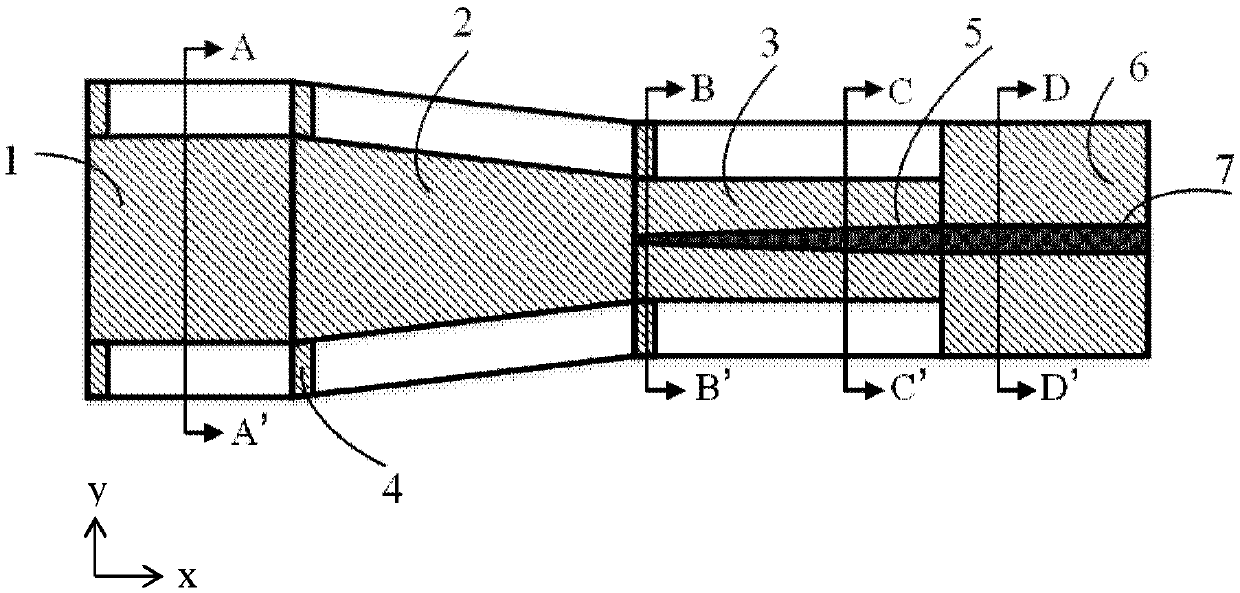
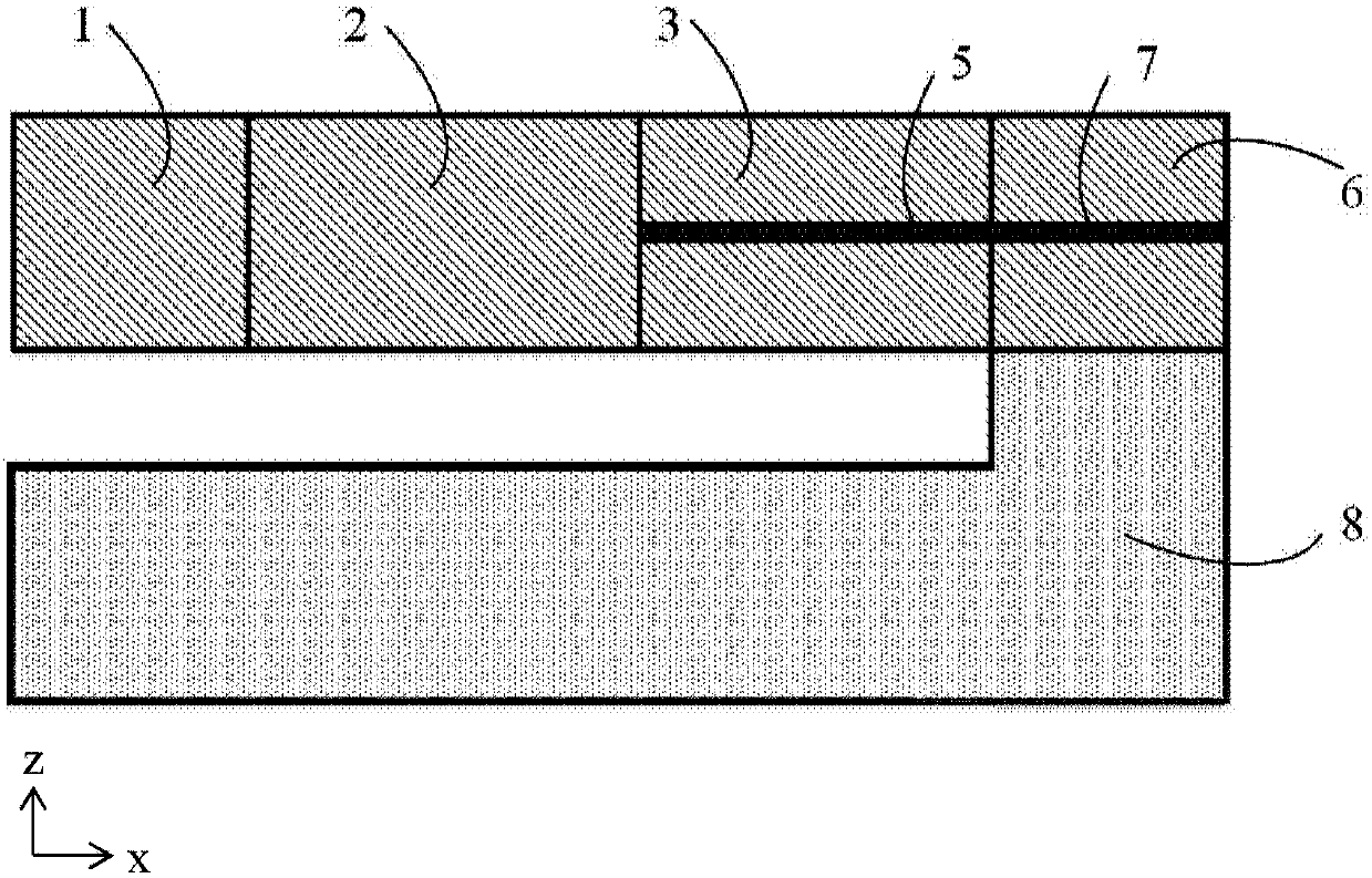
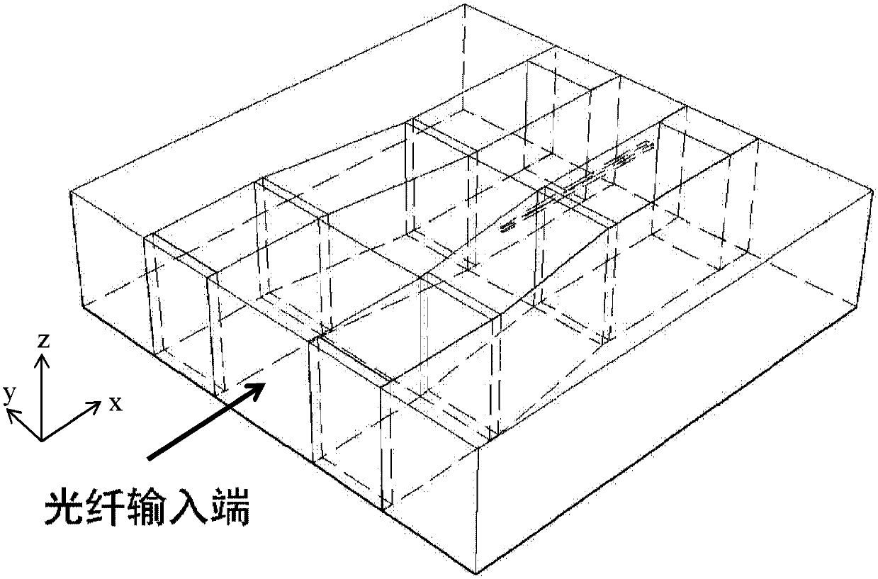
[0030] The present disclosure provides a silicon nanowire waveguide and optical fiber coupling structure and a manufacturing method thereof, which uses the buried oxide layer silicon dioxide and the externally deposited silicon dioxide film to form a silicon dioxide waveguide transition structure, and removes part of the SOI substrate. The silicon layer of the back substrate eliminates the leakage loss, mode field mismatch loss and reflection loss caused by the diffusion of the light field to the substrate. The structure is simple, the design is convenient, the production is relatively easy, and the cost is low, which is conducive to large-scale production and application.

[0031] In order to make the purpose, technical solutions and advantages of the present disclosure clearer, the present disclosure will be further described in detail below in conjunction with specific embodiments and with reference to the accompanying drawings.

[0032] In an exemplary embodiment of the pre...


PUM


Abstract

The invention discloses a coupling structure with a silicon nanowire waveguide and a fiber and a manufacturing method thereof. The coupling structure comprises a first silicon dioxide waveguide beingan input waveguide, a tapered silicon dioxide waveguide, a second silicon dioxide waveguide, a silicon dioxide flat-panel structure, a tapered silicon waveguide, and a silicon output waveguide. One side of the tapered silicon dioxide waveguide is connected with the first silicon dioxide waveguide and the dimension of the cross section is reduced gradually along the light transmission direction; the second silicon dioxide waveguide is connected with the other side of the tapered silicon waveguide and the dimension of the cross section of the second silicon dioxide waveguide is smaller than thatof the first silicon dioxide waveguide; the silicon dioxide flat-panel structure is connected with the second silicon dioxide waveguide; the tapered silicon waveguide coated by the second silicon dioxide waveguide is arranged at a symmetric axis of the second silicon dioxide waveguide and has the cross section with the dimension extending gradually along the light transmission direction; and thesilicon output waveguide coated by the silicon dioxide flat-panel structure is arranged at a symmetric axis of the silicon dioxide flat-panel structure and is connected with the tapered silicon waveguide. The simple coupling structure is designed to be convenient and is manufactured easily with low cost; and large-scale production and application of the coupling structure can be realized easily.

Description

technical field [0001] The disclosure belongs to the technical field of optical fiber communication and integrated optics, and relates to a silicon nanowire waveguide and optical fiber coupling structure and a manufacturing method thereof. Background technique [0002] Traditional waveguides with large cross-sections are usually on the order of hundreds of microns to millimeters. Due to their large bending radii, it is difficult to integrate multiple optical functional devices on a single wafer, which limits the development of large-scale integrated optical circuits. With the advancement of semiconductor processing, silicon nanowire optical waveguides and devices have become one of the hot research fields today. Silicon nanowire waveguides are usually made of silicon SOI (Silicon-on-insulator, SOI) substrates. The refractive index difference between the core layer and the cladding layer is very large, which can form a strong confinement of the optical field, so as to realize...

Claims


Application Information

Patent Timeline
Patent Type & Authority Applications(China)
IPC IPC(8): G02B6/122G02B6/136G02B6/13G02B6/12G02B6/26
Inventor 付鑫杨林丁建峰张磊
Owner INST OF SEMICONDUCTORS - CHINESE ACAD OF SCI
Why Eureka
Try Eureka