
Efficient and energy-saving ultrasonic power supply

A high-efficiency energy-saving, ultrasonic technology, applied in the direction of electrical components, output power conversion devices, cleaning methods using liquids, etc., can solve the problems of low electro-acoustic efficiency, reduced service life, long cleaning time, etc., to achieve aging speed and life Small impact, high electro-acoustic efficiency, and good working effect

Pending Publication Date: 2021-12-10
西安超霸电气科技有限公司
View PDF0 Cites 0 Cited by
  • Summary
  • Abstract
  • Description
  • Claims
  • Application Information

AI Technical Summary

Problems solved by technology

[0002] Ultrasonic cleaning systems or in the field of ultrasonic surface treatment require ultrasonic power supplies to work with ultrasonic vibrators or arrays. Ultrasonic vibrators have the characteristics of resonant frequencies, and existing power supplies cannot accurately work below this frequency, making electroacoustics Low efficiency; at the same time, due to cost considerations, the existing power supply adopts a two-stage structure of rectifier bridge rectification + inverter stage, because the input of the inverter stage is the rectified bun wave, which will make the output That is, the voltage at both ends of the ultrasonic vibrator is overvoltage when the input terminal reaches its peak. This periodic overvoltage has a great impact on the parameter performance of the ultrasonic vibrator and reduces the service life; the fixed frequency output mode of the existing ultrasonic power supply makes the ultrasonic cleaning Uneven distribution in the medium makes the cleaning effect poor, or longer cleaning time is required to achieve the same cleaning effect

Method used


Image

  • Efficient and energy-saving ultrasonic power supply

Examples


Embodiment Construction

[0023] Next, the technical solutions in the embodiments of the present invention will be described in connection with the drawings of the embodiments of the present invention, and it is understood that the described embodiments are merely the embodiments of the present invention, not all of the embodiments. Based on the embodiments in the present invention, those of ordinary skill in the art will belong to the scope of the present invention without all other embodiments obtained in the preparation of creative labor.

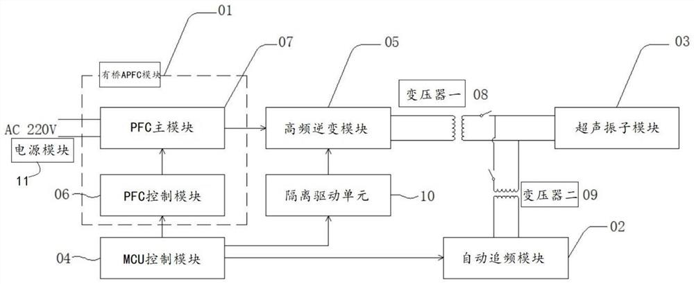
[0024] See figure 1 The present invention provides a technical solution: an efficient energy-saving ultrasonic power source, including the MCU control module 4, a bridge APFC module 1, a high frequency inverter module 5, and an automatic charter module 2, the bridge APFC module 1, The high-frequency inverter module 5 and the automatic changing frequency module 2 are electrically connected to the MCU control module 4;

[0025] The bridge APFC module 1 is electrically ...


PUM


Abstract

The invention discloses an efficient and energy-saving ultrasonic power supply, which belongs to the technical field of ultrasonic power supplies, and comprises an MCU control module, a bridged APFC module, a high-frequency inversion module and an automatic frequency tracking module, wherein the bridged APFC module, the high-frequency inversion module and the automatic frequency tracking module are electrically connected with the MCU control module; and the bridged APFC module converts alternating current mains supply input by the power supply module into high-voltage direct current, the high-voltage direct current flows into the high-frequency inversion module, and the MCU control module acquires a current conversion state of the bridged APFC module. The power supply adopts a two-stage control APFC and high-frequency inversion scheme, and since the output voltage of the APFC is pure direct current, on the one hand, the problems of low power factor and high power consumption of the existing power supply are solved, on the other hand, the problem of periodic overvoltage at two ends of a load caused by alternating current wave crests of the inversion stage is solved, and the influence on the service life of an ultrasonic vibrator due to accelerated depolarization is avoided.

Description

Technical field [0001] The present invention belongs to the technical field of ultrasonic power supply, and more particularly to high efficient energy-saving ultrasonic power supplies. Background technique [0002] Ultrasonic cleaning system or in the field of ultrasonic surface treatment, ultrasonic power supply is required to work with ultrasonic vibrators or arrays, and ultrasonic vibrators have the characteristics of resonant frequencies, and the existing power supply cannot be accurately operated under this frequency, so that electroacoustic The efficiency is low; while the existing power supply is considered for cost, the rectifier bridge rectifier + reverse stage two-stage structure is used, and the input of the inverse transformation is the rectified taro, which will cause the inverse transformation. That is, the voltage across the ultrasonic vibrator is overvoltage of the peak time at the input end, which has a large impact on the parameters of the ultrasonic vibrator, r...

Claims


Application Information

Patent Timeline
IPC IPC(8): H02M1/42H02M5/42B08B3/12
CPCH02M1/4208H02M5/42B08B3/12
Inventor 李凯利王禾王东升吴世杰黄淑梅
Owner 西安超霸电气科技有限公司
Learn More