Acoustic radiation plate of dual-frequency ultrasonic radiator

A radiator sound and dual-frequency ultrasonic technology, which is applied in the direction of ultrasonic therapy, treatment, massage auxiliary products, etc., can solve the problems that the dual-frequency ultrasonic radiator acoustic radiating board has not been found in literature reports and other issues

Inactive Publication Date: 2004-06-02
SHANGHAI JIAO TONG UNIV
View PDF0 Cites 0 Cited by
  • Summary
  • Abstract
  • Description
  • Claims
  • Application Information

AI Technical Summary

Problems solved by technology

[0005] The technologies involved in the above-mentioned documents are all applicable to single-frequency ultrasonic radiators, and so far no literature reports applicable to the acoustic radiating panels of dual-frequency ultrasonic radiators have been found.

Method used


Image

  • Acoustic radiation plate of dual-frequency ultrasonic radiator
  • Acoustic radiation plate of dual-frequency ultrasonic radiator
  • Acoustic radiation plate of dual-frequency ultrasonic radiator

Examples


Embodiment Construction

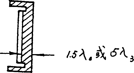
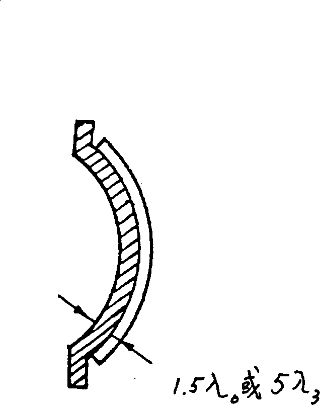
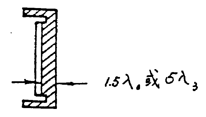
[0012] Such as figure 1 , figure 2 As shown, the plate-shaped non-focused or bowl-shaped focused piezoelectric ceramic transducer vibrator has multiple resonant frequencies (fundamental frequency f 0 and overtone frequency f 3 , f 5 , f 7 ,...) characteristics that allow it to work at the fundamental frequency f 0 and the first overtone frequency f 3 , to calculate the half-wavelength λ of the acoustic radiating panel material at these two frequencies 0 / 2 and λ 3 The least common multiple of / 2, as the thickness of the acoustic radiation plate of the transducer, the thickness of the acoustic radiation plate is equal to 1.5 times the wavelength of the fundamental frequency or 5 times the wavelength of the first overtone frequency, which can meet the dual-frequency working conditions and realize high-power The purpose of high-power dual-frequency ultrasonic emission.


PUM


Abstract

An acoustic radiation plate of dual-frequency ultrasonic radiator is disclosed. Its thickness is equal to 1.5 times of wavelength of base frequency or equal to 5 times of wavelength of the first overtone frequency.

Description

technical field [0001] The invention relates to a double-frequency ultrasonic radiator sound radiation plate. It belongs to the professional field of medical equipment. Background technique [0002] In the technical background, traditional ultrasonic transducers for power ultrasonic physiotherapy, in order to obtain higher emission efficiency, protect the piezoelectric vibrator from the erosion of the medium, and provide mechanical support for the vibrator to facilitate installation, usually use integer multiples of half the wavelength The metal plate with thickness (nλ / 2) is made into an acoustic radiation plate, so that the ultrasonic energy emitted by the piezoelectric vibrator can be effectively transmitted to the medium. This has become common sense in the design of ultrasonic transducers, such as: similar technical documents obtained through retrieval: [0003] 1. PNT Wells, Biomedical Ultrasonics, Academic Press, p471, 1977. [0004] 2. Guo Zhiying, Yu Shixun, Gao ...

Claims


Application Information

Patent Timeline
IPC IPC(8): A61H23/00A61N7/00B06B1/06
Inventor 寿文德钱德初
Owner SHANGHAI JIAO TONG UNIV
Why Eureka
Try Eureka