
Combined heat dissipation system, electrical equipment, air conditioner and heat dissipation method

A heat dissipation system and electrical equipment technology, which is applied in the structural parts of electrical equipment, electrical components, cooling/ventilation/heating transformation, etc., can solve the problems of inability to meet high-efficiency heat dissipation, single heat dissipation mode of heat dissipation system, etc., and avoid low heat dissipation efficiency , Improve the effect of cooling efficiency

Pending Publication Date: 2021-12-10
GREE ELECTRIC APPLIANCES INC
View PDF0 Cites 0 Cited by
  • Summary
  • Abstract
  • Description
  • Claims
  • Application Information

AI Technical Summary

Problems solved by technology

[0004] This application provides a combined heat dissipation system, electrical equipment, air conditioner and heat dissipation method, which are used to solve the technical problem that the heat dissipation system of the existing electrical equipment has a single heat dissipation method and cannot meet the needs of efficient heat dissipation

Method used


Image

  • Combined heat dissipation system, electrical equipment, air conditioner and heat dissipation method
  • Combined heat dissipation system, electrical equipment, air conditioner and heat dissipation method
  • Combined heat dissipation system, electrical equipment, air conditioner and heat dissipation method

Examples


Embodiment Construction

[0049] In order to make the purpose, technical solution and advantages of the present application clearer, the technical solution of the present application will be described in detail below. Apparently, the described embodiments are only some of the embodiments of this application, not all of them. Based on the embodiments in the present application, all other implementation manners obtained by persons of ordinary skill in the art without creative efforts fall within the protection scope of the present application.

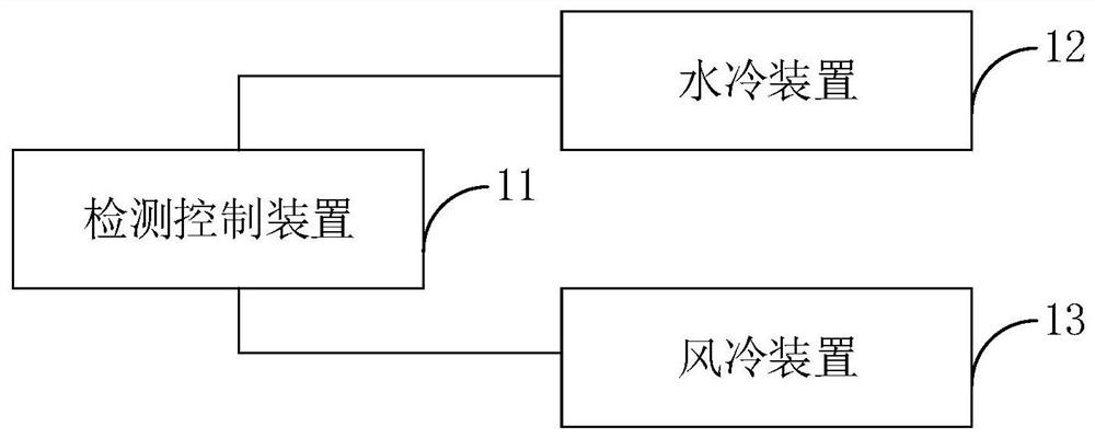
[0050] see figure 1 It is a structural schematic diagram of a combined heat dissipation system provided by an embodiment of the present application. The embodiment of the present application provides a combined heat dissipation system. As shown in the figure, the system may include: a detection and control device 11 , and a water cooling device 12 and an air cooling device 13 respectively connected to the detection and control device 11 .

[0051] Wherein, the ...


PUM


Abstract

The invention relates to a combined heat dissipation system, electrical equipment, an air conditioner and a heat dissipation method. The combined heat dissipation system comprises a detection control device, a water cooling device and an air cooling device, wherein the water cooling device and the air cooling device are connected with the detection control device, the detection control device is used for detecting the temperature in to-be-cooled equipment and controlling the water cooling device to cool the to-be-cooled equipment when detecting that the temperature in the to-be-cooled equipment exceeds a first threshold value, the water cooling device is used for performing water circulation heat dissipation under the control of the detection control device, the detection control device is further used for detecting the water temperature in the water cooling device, and controlling the air cooling device to cool the to-be-cooled equipment when it is detected that the water temperature exceeds a second threshold value or the temperature in the to-be-cooled equipment exceeds a third threshold value, and the air cooling device is used for exhausting air and dissipating heat under the control of the detection control device. According to the invention, the defects caused by a single heat dissipation mode are overcome, the heat dissipation efficiency is improved, and a guarantee is provided for normal work of the equipment to be subjected to heat dissipation.

Description

technical field [0001] The present application relates to the technical field of electrical equipment, in particular to a combined heat dissipation system, electrical equipment, an air conditioner and a heat dissipation method. Background technique [0002] With the improvement of industrial automation level, all kinds of electrical equipment emerge in an endless stream, which brings great convenience to people's work and life. [0003] In the related art, most of the existing electrical equipments need to dissipate heat in real time during the working process, so as to avoid damage to the electrical equipments due to overheating. However, the heat dissipation effect of the heat dissipation system of this type of electrical equipment is usually not ideal, and the heat dissipation method is single, which cannot meet the needs of efficient heat dissipation. It is easy to cause premature aging of internal components due to lack of timely and rapid cooling during use. Then redu...

Claims


Application Information

Patent Timeline
IPC IPC(8): H05K7/20
CPCH05K7/20281H05K7/20209H05K7/20136
Inventor 曲鹏宇梅正茂李百宇
Owner GREE ELECTRIC APPLIANCES INC
Learn More