Forging blank preheating device for hydraulic hose joint production and processing
A hydraulic hose and preheating technology, which is applied in the field of forging blank preheating devices, can solve problems such as unfavorable forging of shaft forgings, uneven heating of forgings, and adhesion of adjacent forgings, so as to achieve high work efficiency and ensure heating effect, the effect of avoiding offset
- Summary
- Abstract
- Description
- Claims
- Application Information
AI Technical Summary
Problems solved by technology
Method used
Image

Examples
Embodiment Construction
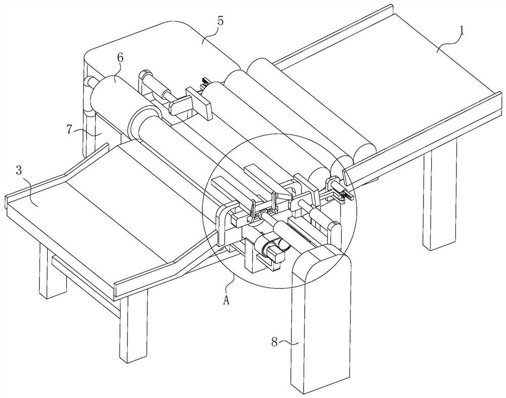
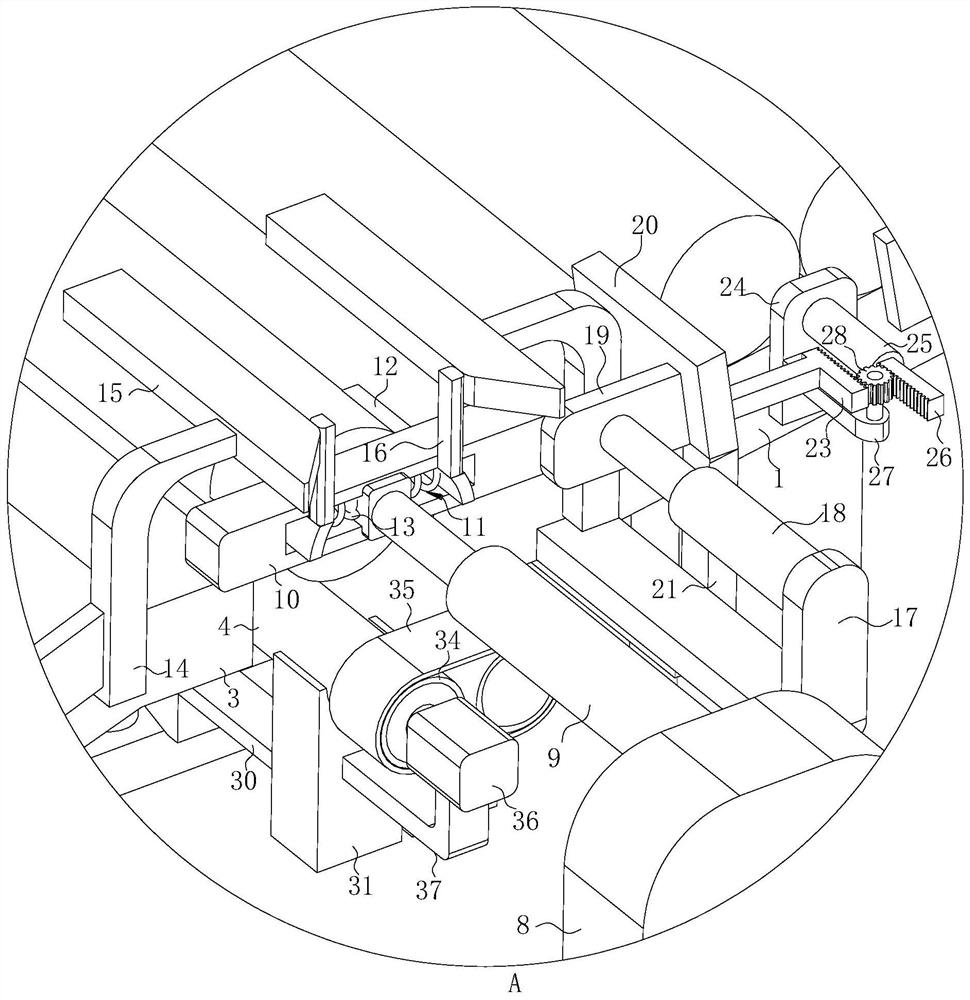
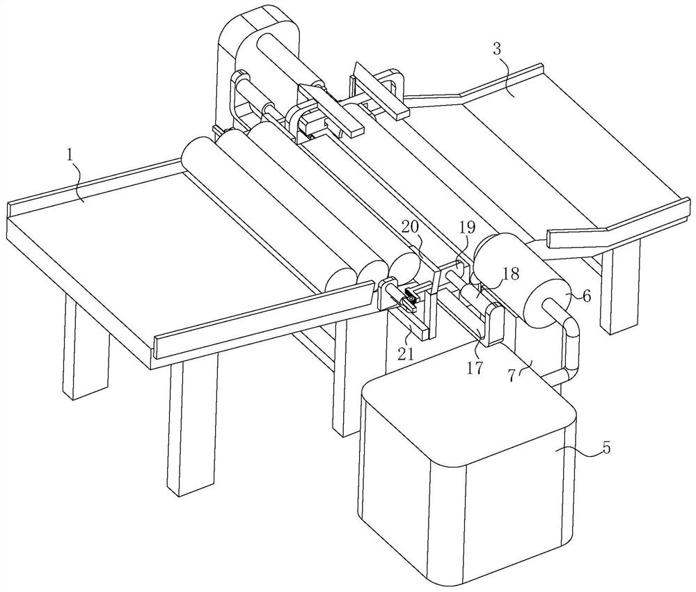
[0025] see Figure 1-7 , the present invention provides a technical solution: a preheating device for forging blanks used in the production and processing of hydraulic hose joints, including a feeding bracket 1, which is in an inclined posture, and the inner wall of the feeding bracket 1 passes through the I-shaped The connecting plate 2 is fixedly connected with the feeding bracket 3, and the feeding bracket 3 is arranged obliquely. There are two rotating rollers 4 before the feeding bracket 1 and the feeding bracket 3, and the rear side of the rotating roller 4 is provided for uniformly heating the circumference of the rotating roller 4. The heating mechanism, the front side of the rotating roller 4 is provided with a pushing mechanism for pushing the shaft forging on the top of the rotating roller 4 into the heating mechanism for heating, and the outer side of the feeding bracket 3 is connected with a shaft forging to enter two rotating rollers 4 at a time. upper opening an...
PUM
 Abstract
Description
Claims
Application Information