


Quick Research
Generate reliable direction feasibility study reports for your R&D in just a few steps.

Technical Q&A
Discover and master advanced knowledge NOW. Basics, ideas, possibilities, all at once.

Find Solutions
As an expert in R&D theories, this can generate solutions to your technical problems instantly.

Evaluate Feasibility
Analyze your overall solution with one click, know your potential R&D risks in advance.

Monitor Landscape
Get weekly tech updates, stay abreast of the latest tech innovations and key insights.
Locking mechanism and locking method
A technology of locking mechanism and limiting body, which is applied in turning equipment, tool holder accessories, metal processing equipment, etc., can solve the problems of low locking efficiency and achieve the effect of high locking efficiency
- Summary
- Abstract
- Description
- Claims
- Application Information
AI Technical Summary
Problems solved by technology
Method used
Image

Examples
Embodiment 1
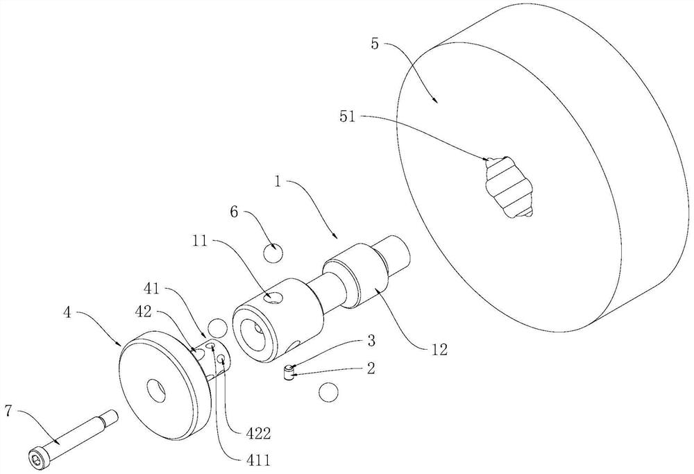
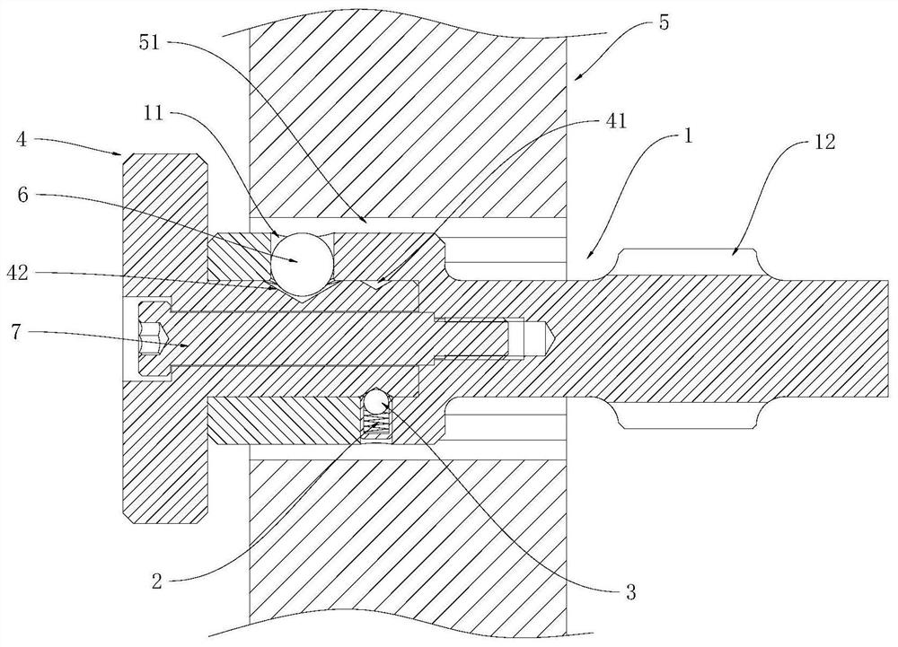
[0033] combined with Figure 1-3 , this embodiment provides a locking mechanism, including:
[0034] shaft one 1, shaft one 1 is evenly distributed with through holes 11 along the radial direction;
[0035] Spring 2, one end of spring 2 is connected to shaft one 1, and the other end of spring 2 is provided with limiter one 3;
[0036] Rotate the shaft 2 4 connected to the shaft 1, and the shaft 2 4 is provided with a groove 1 41 and a groove 2 42 that cooperate with the limiter 3 along the radial direction;
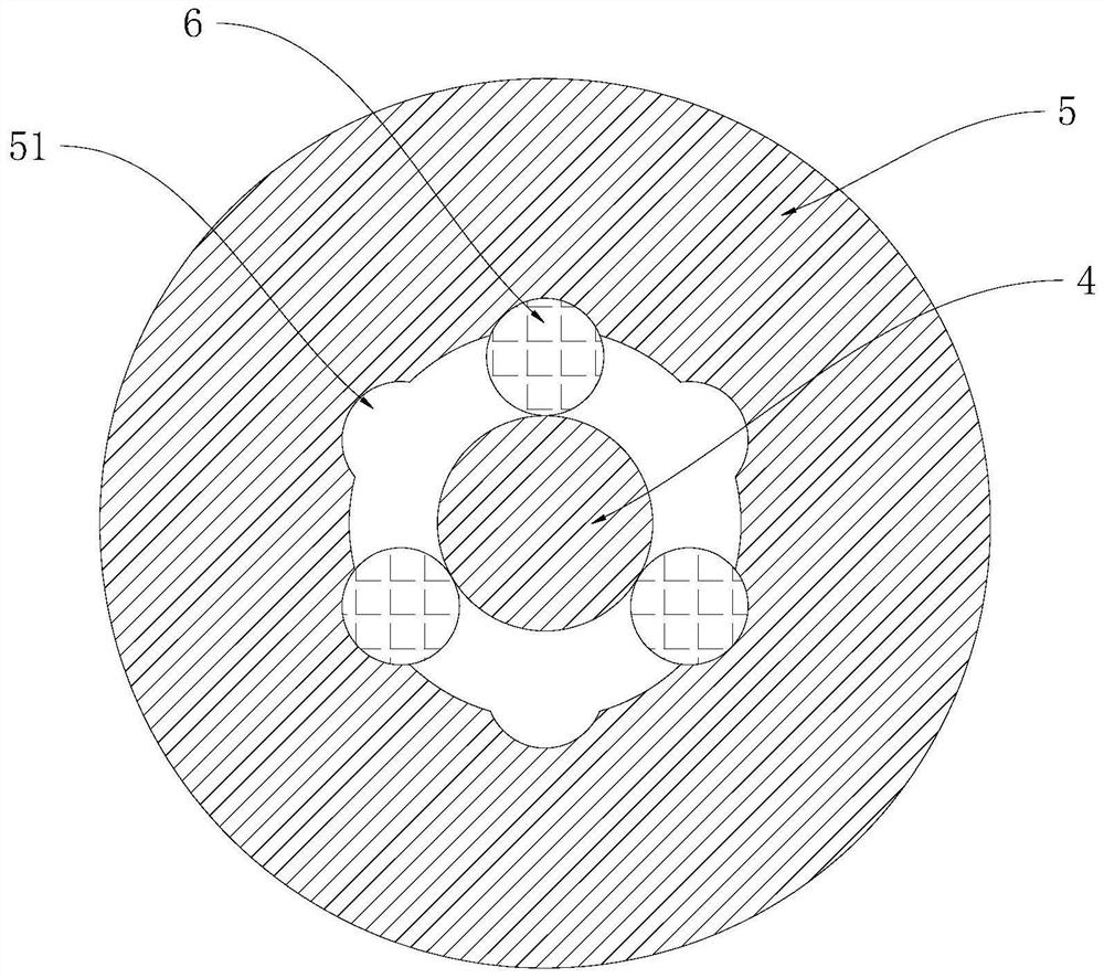
[0037] The casing 5 is sleeved on the outside of the shaft 1, and the casing 5 is provided with a groove 3 51;
[0038] It is movably connected to the second limiting body 6 in the through hole 11.
[0039] Specifically, the through hole 11 is carried by the shaft one 1, which can ensure the stability of the through hole 11. Because the limit body 2 6 is movably connected in the through hole 11, the through hole 11 is used to accommodate the limit body 2 6, ensuring th...
Embodiment 2
[0058] combined with Figure 1-3 , this embodiment provides a locking method, according to the technical solution of Embodiment 1, including:
[0059] Rotate the shaft two 4, so that the limit body two 6 cooperates with the groove two 42, so that the limit body one 3 cooperates with the first groove one 411 of the groove one 41; or,
[0060] Rotate the shaft 2 4 to make the limit body 2 6 cooperate with the groove 3 51 , and make the limit body 1 3 cooperate with the second groove 412 of the groove 1 41 .
[0061] Specifically, rotate the shaft 2 4 so that the limit body 2 6 and the groove 2 42 cooperate, and make the limit body 1 3 cooperate with the first groove 411 of the groove 41. At this time, the shaft 1 and the housing 5 can be relatively movable. If the locking mechanism is used for cutting equipment such as lathes, milling machines or magnetic base drilling machines, the feed mechanism of the cutting equipment is in a clutch state; the rotating shaft 2 4 makes the l...
PUM
 Abstract
Description
Claims
Application Information
 - R&D Engineer
- R&D Manager
- IP Professional
- Industry Leading Data Capabilities
- Powerful AI technology
- Patent DNA Extraction
Browse by: Latest US Patents, China's latest patents, Technical Efficacy Thesaurus, Application Domain, Technology Topic, Popular Technical Reports.
© 2024 PatSnap. All rights reserved.Legal|Privacy policy|Modern Slavery Act Transparency Statement|Sitemap|About US| Contact US: help@patsnap.com