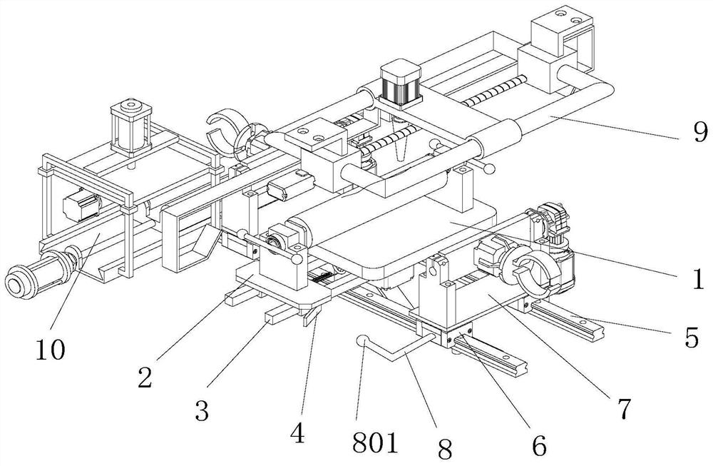
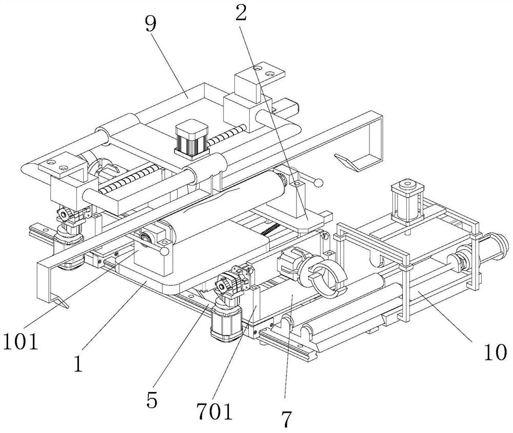
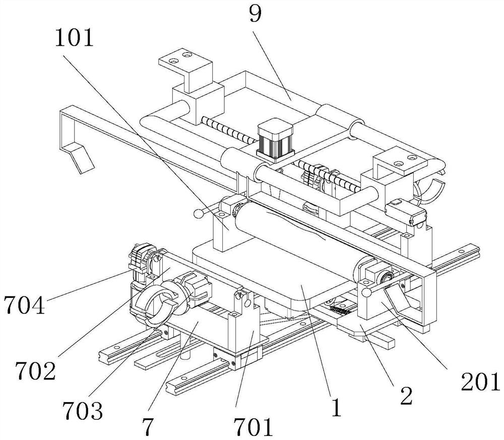
Laser cladding synchronous grinding system for roller repair and grinding process of laser cladding synchronous grinding system

A technology of laser cladding and roll, which is applied in the field of roll processing, can solve the problems of complex structure of metal roll processing equipment, troublesome repairs, waste of equipment resources, etc., and achieve the effect of avoiding manual delivery of workpieces, increasing contact area, and saving equipment resources

Active Publication Date: 2021-12-14
YIXING YONGCHANG ROLL
View PDF15 Cites 2 Cited by
  • Summary
  • Abstract
  • Description
  • Claims
  • Application Information

AI Technical Summary

Problems solved by technology

[0002] With the development of industrial technology, metal rolls are required for sheet metal processing and workpiece shaping. Metal rolls are made of solid metal, and the weight of metal rolls is heavy. Moreover, the structure of metal roll processing equipment is complicated. The material is relatively laborious, and it is difficult for the hands of the staff to reach into the equipment with complex structures to operate;
Moreover, there are roughly two types of damage to the metal roll. The first case is that there are strip marks on the metal roll. This kind of damage will cause the metal roll to deform and it is troublesome to repair. This kind of scratch will not cause deformation of the metal roll, and it is relatively simple to repair. The two damages need to be repaired on two kinds of maintenance equipment, which wastes equipment resources

Method used


Image

  • Laser cladding synchronous grinding system for roller repair and grinding process of laser cladding synchronous grinding system
  • Laser cladding synchronous grinding system for roller repair and grinding process of laser cladding synchronous grinding system
  • Laser cladding synchronous grinding system for roller repair and grinding process of laser cladding synchronous grinding system

Examples


Embodiment Construction

[0035] In order to make the object, technical solution and advantages of the present invention clearer, the present invention will be further described in detail below in conjunction with the accompanying drawings and embodiments. It should be understood that the specific embodiments described here are only used to explain the present invention, not to limit the present invention.

[0036] In describing the present invention, it should be understood that the terms "longitudinal", "transverse", "upper", "lower", "front", "rear", "left", "right", "vertical", The orientations or positional relationships indicated by "horizontal", "top", "bottom", "inner", "outer", etc. are based on the orientations or positional relationships shown in the drawings, and are only for the convenience of describing the present invention, rather than indicating or It should not be construed as limiting the invention by implying that a referenced device or element must have a particular orientation, be...


PUM


Abstract

The invention discloses a laser cladding synchronous grinding system for roller repair and a grinding process of the laser cladding synchronous grinding system, and belongs to the field of roller repairing. The laser cladding synchronous grinding system for roller repair comprises a base table plate fixedly connected with a building, two extending guide rails are arranged at the bottom end of the base table plate, a clamping table is arranged at the top ends of the extending guide rails, inserting square sleeves arranged on the extending guide rails in a sleeving mode are arranged at the bottom end of the clamping table, the inserting square sleeves are in sliding connection with the extending guide rails, a fixed shaft seat is arranged at the top end of the base table plate, a movable shaft seat is arranged at the top end of the clamping table, two transposition guide rails are fixedly mounted at the bottom end of the base table plate, the transposition guide rails are sleeved with two sets of transposition sliding blocks, the transposition sliding blocks are slidably connected with the transposition guide rails, a carrying table is fixedly installed at the top end of each set of transposition sliding blocks, a laser heating assembly is arranged above the base table plate, and a grinding assembly is arranged on one side of the base table plate.

Description

technical field [0001] The invention relates to the field of roll processing, in particular to a laser cladding synchronous grinding system for roll repair and a grinding process thereof. Background technique [0002] With the development of industrial technology, metal rolls are required for sheet metal processing and workpiece shaping. Metal rolls are made of solid metal, and the weight of metal rolls is heavy. Moreover, the structure of metal roll processing equipment is complicated. The material is relatively laborious, and it is difficult for the hands of the staff to reach into the equipment with complex structures to operate; Moreover, there are roughly two types of damage to the metal roll. The first case is that there are strip marks on the metal roll. This kind of damage will cause the deformation of the metal roll and it is more troublesome to repair. This kind of scratches will not cause deformation of the metal roll, and it is relatively simple to repair. The ...

Claims


Application Information

Patent Timeline
Patent Type & Authority Applications(China)
IPC IPC(8): B24B5/16B24B5/35B24B41/06B24B47/08B24B47/12C23C24/10
CPCB24B5/167B24B5/355B24B41/067B24B47/12C23C24/10B24B47/04B24B47/22
Inventor 邵黎军朱健李瑞峰
Owner YIXING YONGCHANG ROLL
Why Eureka
Try Eureka