A synchronous processing device for yarn conduction and feeding
A synchronous processing and yarn technology, applied in textiles and papermaking, etc., can solve the problems of affecting yarn strength, affecting yarn flatness, structural drawing, etc., and achieve the effect of ensuring efficient processing and ensuring strength
- Summary
- Abstract
- Description
- Claims
- Application Information
AI Technical Summary
Problems solved by technology
Method used
Image
Examples
Embodiment 1
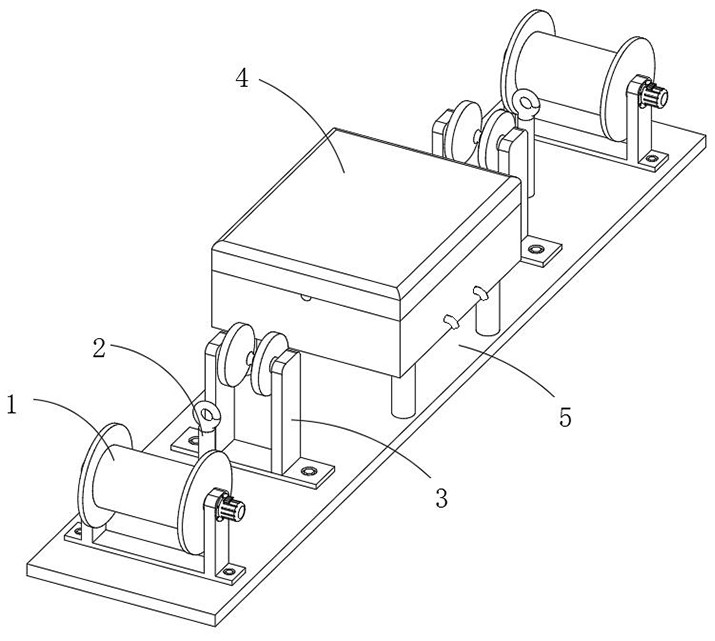
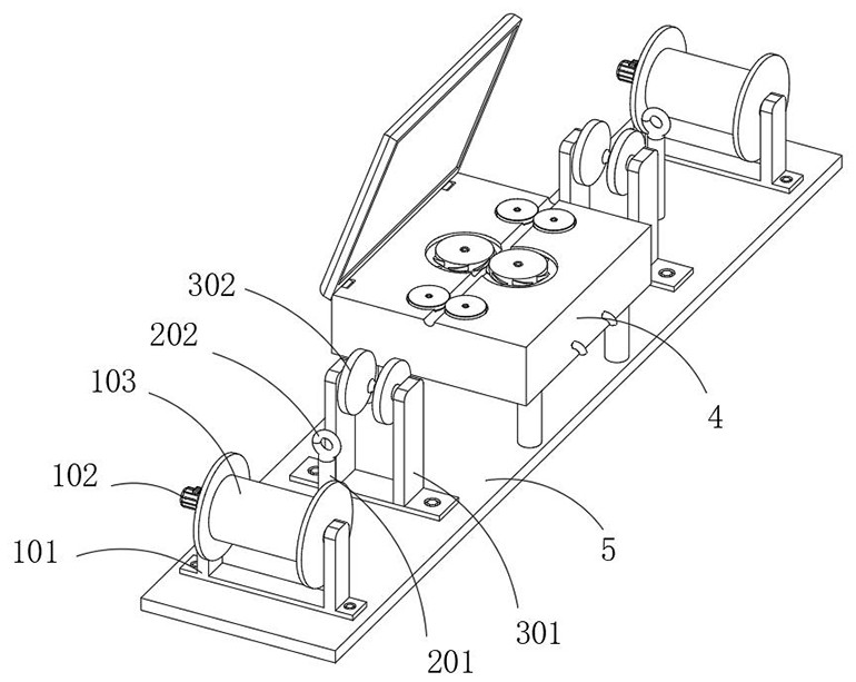
[0027] This embodiment provides a specific structure of a yarn conduction and wire feeding synchronization processing device, such as Figure 1-5 As shown, it includes a processing assembly 4 and a take-up and pay-off assembly 1, wherein the processing assembly 4 is used to trim the part of the yarn around the yarn. Component 1 is divided into a pay-off part and a take-up part. The pay-off part winds up the untreated yarn and pays out the yarn, so that it passes through the processing component 4 and is processed by the take-up part;
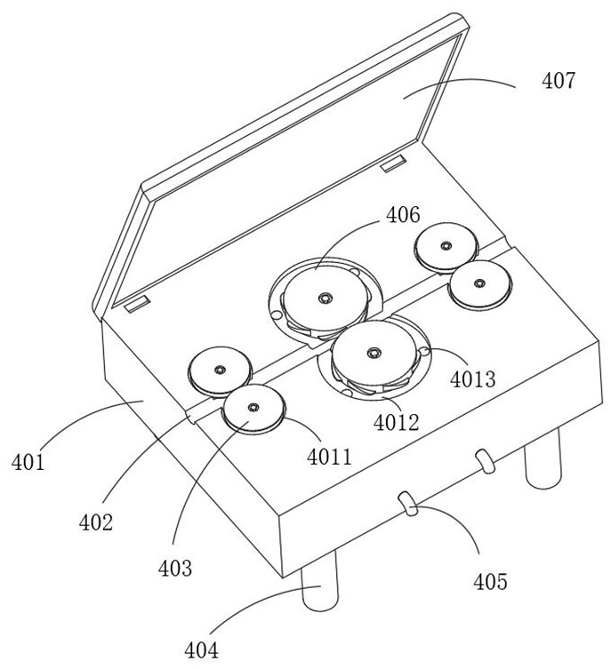
[0028] The processing assembly 4 includes a processing box 401. The upper surface of the processing box 401 is provided with a wire groove 402 along the length direction. The upper surface of the processing box 401 is located on both sides of the wire groove 402. Two second installation grooves 4012 are opened. Two second installation grooves 4012 are rotatably installed with a cutter head 406, the outer wall of the cutter head 406 has a blade 4...
Embodiment 2
[0032] On the basis of Embodiment 1, in this embodiment, the processing component 4 further includes a flying yarn processing mechanism, which is used for processing the flying yarn generated when processing the yarn, and the flying yarn processing mechanism includes a yarn removing channel 4013 and a yarn discharging channel. Tube 405, wherein the yarn removal channel 4013 is located inside the processing box 401, one end of the yarn removal channel 4013 is located in the second installation groove 4012, and the other end is located on the outer wall of the processing box 401. The yarn removal channel 4013 is communicated with each other, a negative pressure air valve is arranged inside the processing box 401 at the yarn removal channel 4013, and a negative pressure fan adapted to the negative pressure air valve is installed inside the processing box 401.
[0033] The processing assembly 4 also includes a thread stabilization mechanism, which is used to stabilize the yarn pass...
Embodiment 3
[0039] On the basis of Embodiment 1, in this embodiment, both the wire pay-off part and the wire take-up part in the wire take-up and pay-off assembly 1 include wire roller frames 101, and the two wire roller frames 101 are located on both sides of the processing box 401 respectively. The roller frame 101 has a U-shaped structure. A wire roller 103 is rotatably installed between two vertical ends of the wire roller frame 101. A wire-reeling and paying-off motor 102 is installed outside one of the vertical ends of the wire roller frame 101. The wire-receiving and paying-off motor 102 The output shaft is connected with the rotating shaft of the thread roller 103. In the process of conducting wire feeding, the two take-up and pay-off motors 102 run at the same time, and the rotational speeds of the two take-up and pay-off motors 102 are kept the same, so as to ensure that the yarn can be conducted at a uniform speed .
[0040] It also includes a central conduction assembly 2, whi...
PUM
 Abstract
Description
Claims
Application Information
 - R&D
- Intellectual Property
- Life Sciences
- Materials
- Tech Scout
- Unparalleled Data Quality
- Higher Quality Content
- 60% Fewer Hallucinations
Browse by: Latest US Patents, China's latest patents, Technical Efficacy Thesaurus, Application Domain, Technology Topic, Popular Technical Reports.
© 2025 PatSnap. All rights reserved.Legal|Privacy policy|Modern Slavery Act Transparency Statement|Sitemap|About US| Contact US: help@patsnap.com


