
Kitchen waste treatment device

A technology of kitchen waste and processing device, applied in the direction of presses, manufacturing tools, etc., can solve the problems of incomplete solid-liquid separation of waste, and achieve the effect of easy cleaning

Pending Publication Date: 2021-12-14
安必思环保科技(北京)有限公司
View PDF7 Cites 1 Cited by
  • Summary
  • Abstract
  • Description
  • Claims
  • Application Information

AI Technical Summary

Problems solved by technology

[0004] The purpose of the present invention is to provide a kitchen waste treatment device, which solves the technical problem of incomplete solid-liquid separation of waste existing in the prior art

Method used


Image

  • Kitchen waste treatment device
  • Kitchen waste treatment device

Examples


Embodiment Construction

[0026] In order to make the purpose, technical solution and advantages of the present invention clearer, the technical solution of the present invention will be described in detail below. Apparently, the described embodiments are only some of the embodiments of the present invention, but not all of them. Based on the embodiments of the present invention, all other implementations obtained by persons of ordinary skill in the art without making creative efforts fall within the protection scope of the present invention.

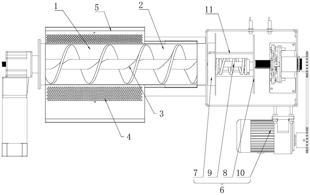
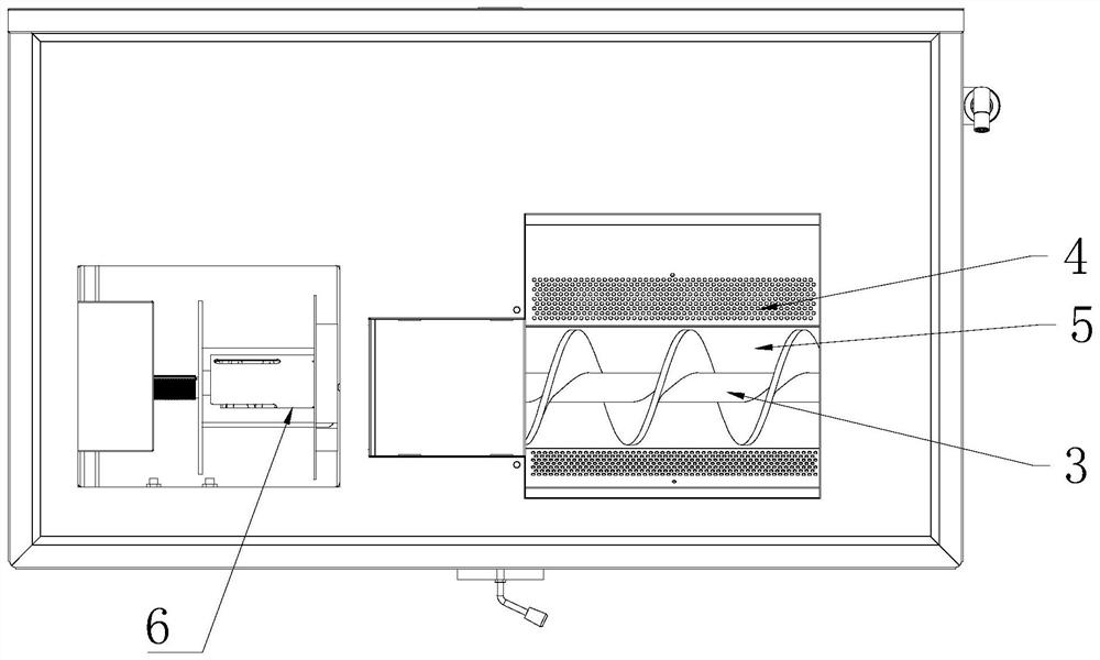
[0027] A specific embodiment of the present invention provides a kitchen waste treatment device, combined with the figure 1 with attached figure 2 As shown, it includes a separation chamber 1, a pre-compression chamber 2, and an auger 3. The separation chamber 1 is used to receive the solid-liquid mixed kitchen waste poured in by the user, and at the same time perform preliminary solid-liquid separation. The side wall and bottom of the separation chamber 1 It...


PUM


Abstract

The invention provides a kitchen waste treatment device, relates to the technical field of waste treatment equipment, and solves the technical problem of incomplete solid-liquid separation of waste in the prior art. The kitchen waste treatment device comprises a separation cavity, a pre-pressing cavity and an auger, wherein the separation cavity is communicated with the pre-pressing cavity; the auger is arranged in the separation cavity and the pre-pressing cavity and pushes kitchen waste to pass through the separation cavity and the pre-pressing cavity; and the screw pitch of the part, located in the pre-pressing cavity, of the auger is smaller than the screw pitch of the part, located in the separation cavity, of the auger. The kitchen waste separation device is used for treating the kitchen waste, through the variable-pitch design of the auger, the waste is preliminarily extruded in the conveying process, liquid waste is discharged from separation holes, and separation treatment of the kitchen waste is completed more thoroughly.

Description

technical field [0001] The invention relates to the technical field of garbage treatment equipment, in particular to a kitchen garbage treatment device. Background technique [0002] At present, the squeeze reduction mechanism of kitchen waste treatment equipment mostly uses a conveyor with a shell full of small holes as the main component to complete the waste squeeze reduction process. Its working principle is to move the material (food waste) to the tail of the conveyor driven by the operation of the conveying device, and the material behind pushes the material in the front, and a squeezing force is generated between the blocking device (tail plate of the conveyor), so that the garbage inside The liquid garbage (mainly oil and water) is squeezed out and the volume is compressed at the same time to complete the process of dehydration and solid garbage reduction. In the whole process, the extrusion between the tail blocking device and the conveying device is completely req...

Claims


Application Information

Patent Timeline
Patent Type & Authority Applications(China)
IPC IPC(8): B30B9/14B30B9/30B30B15/00B30B15/32
CPCB30B9/14B30B9/121B30B9/3089B30B9/3014B30B9/3003
Inventor 黄志勇杨存蛟
Owner 安必思环保科技(北京)有限公司
Learn More