Continuous metal film printing device

A metal thin film and printing device technology, applied in printing, printing machines, rotary printing machines, etc., can solve the problems of low printing quality and low printing efficiency, and achieve the effect of high printing arrangement quality and difficult position deviation

Inactive Publication Date: 2021-12-14
刘彪
View PDF0 Cites 0 Cited by
  • Summary
  • Abstract
  • Description
  • Claims
  • Application Information

AI Technical Summary

Problems solved by technology

[0003] After the metal film is produced, it is often printed according to the demand. The existing film printing device has low printing efficiency and low printing quality. Therefore, the present invention proposes a continuous metal film printing device that can solve the above problems

Method used


Image

  • Continuous metal film printing device
  • Continuous metal film printing device
  • Continuous metal film printing device

Examples


Embodiment 1

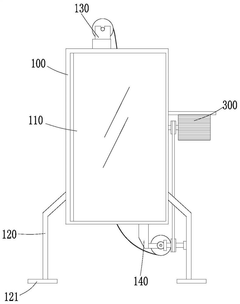
[0043] The present invention provides a technical solution: a continuous metal thin film printing device, including a housing 100, an opening is provided on the front side of the housing 100, a supporting leg 120 is provided at the bottom of the housing 100, and a backing plate 121 is provided at the lower end of the supporting leg 120 ;

[0044] The first fixed frame 130, the first fixed frame 130 is arranged on the upper end of the housing 100, the film raw material cylinder 131 is placed on the first fixed frame 130, and the first fixed frame 130 side is provided with a feed pipe 132, the feed pipe 132 extends vertically into the casing 100 for introducing the film raw material into the casing 100;

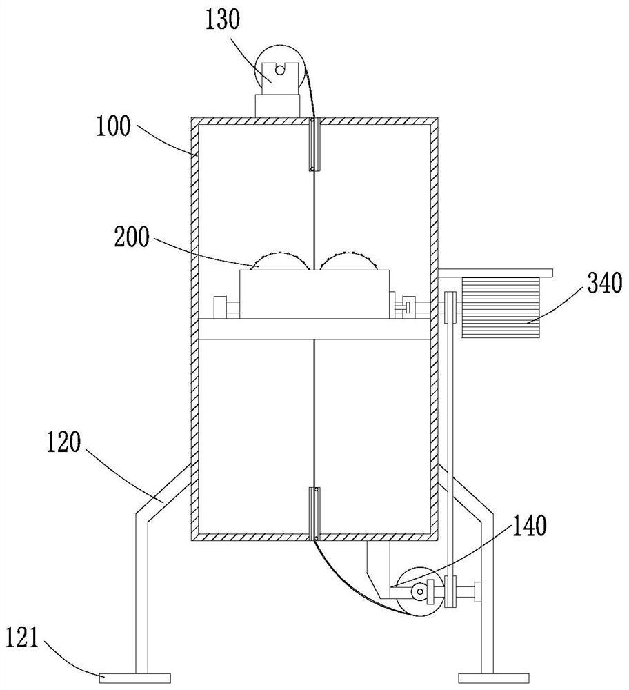
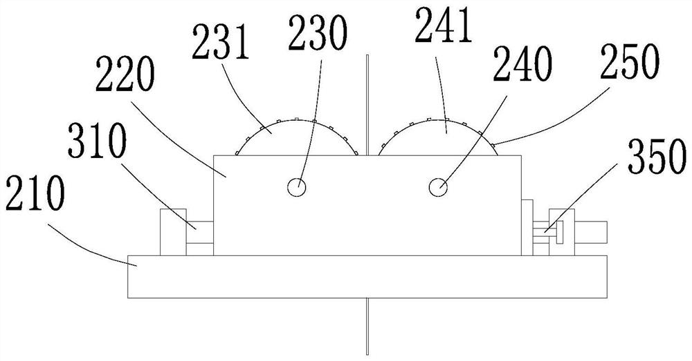
[0045] The printing mechanism 200, the printing mechanism 200 is arranged inside the casing 100, and is used for double-sided printing on the film original material; Vertical support plate 220, the second rotation lever 230 and the third rotation lever 240 are rotated on the v...

Embodiment 2

[0049] On the basis of Embodiment 1, a transparent observation window 110 is installed on the opening, and the support leg 120 is fixed to the ground through the connecting plate. .

[0050] Specifically, the feed pipe 132 and the discharge pipe 142 play a limiting role on the metal film entering the housing 100, and the metal film plays a role in passing through the feed pipe 132 and the discharge pipe 142 through the set guide roller 150. The guiding effect makes the metal film maintain continuous and stable feeding and discharging during printing, the position deviation is not easy to occur, and the printing arrangement quality is high; the printing situation in the casing 100 can be observed in real time through the transparent observation window 110 .

Embodiment 3

[0052] On the basis of Embodiment 1 or Embodiment 2, the driving mechanism 300 includes a first rotating rod 310 rotatably arranged on the lateral support plate 210, and a driving source 340 arranged on the outer wall of the housing 100. The output shaft of the driving source 340 is connected to the first A rotating rod 310 is driven and connected, the first rotating rod 310 is provided with a first worm segment 320 and a second worm segment 330 at intervals, the second rotating rod 230 is fixedly connected with the first worm wheel 232, and the third rotating rod 240 The second worm wheel 242 is fixedly connected, the first worm wheel 232 meshes with the first worm segment 320, and the second worm wheel meshes with the second worm wheel 242;

[0053] The inner sides of the first printing wheel 231 and the second printing wheel 241 are provided with connecting sleeves, and the connecting sleeves are connected with the second rotating rod 230 and the second rotating rod 230 thro...


PUM


Abstract

The invention discloses a continuous metal film printing device. The continuous metal film printing device comprises a shell, a first fixing frame, a printing mechanism and a second fixing frame, wherein an opening is formed in the front side of the shell, supporting legs are arranged at the bottom of the shell, the first fixing frame is arranged at the upper end of the shell, a film raw material barrel is rotationally placed on the first fixing frame, a feeding pipe is arranged on one side of the first fixing frame, the feeding pipe vertically extends into the shell and is used for guiding a thin film raw material into the shell, the printing mechanism is arranged in the shell and is used for conducting double-face printing on the thin film raw material, the second fixing frame is arranged at the upper end of the shell, a thin film winding drum is rotationally placed on the second fixing frame, a discharging pipe is arranged on one side of the second fixing frame, and the discharging pipe vertically extends into the shell and used for guiding a printing film onto the film winding drum. The continuous metal film printing device performs double-sided printing on a film raw material, and is good in printing effect, high in efficiency and high in quality.

Description

technical field [0001] The invention relates to the technical field of metal thin film printing, in particular to a continuous metal thin film printing device. Background technique [0002] Metallic films are used around the world to protect and package food, cosmetics and chemicals; food metal films wrap food. [0003] After the metal film is produced, pattern printing is often performed according to the requirements. The existing film printing device has low printing efficiency and low printing quality. Therefore, the present invention proposes a continuous metal film printing device that can solve the above problems. Contents of the invention [0004] The object of the present invention is to provide a continuous metal thin film printing device to solve the problems raised in the above-mentioned background technology. [0005] In order to achieve the above object, the present invention provides the following technical solutions: a continuous metal thin film printing de...

Claims


Application Information

Patent Timeline
Patent Type & Authority Applications(China)
IPC IPC(8): B41F5/04B65H23/26B65H23/28B65H23/032
CPCB41F5/04B65H23/26B65H23/28B65H23/032B65H2701/173B65H2701/1133
Inventor 刘彪
Owner 刘彪
Why Eureka
Try Eureka