Five-axis linkage quenching machine tool carried with DSP and digital high-frequency power supply
A high-frequency power supply and five-axis linkage technology, which is applied in the field of hardening machine tools, can solve the problems of inconvenient parts fixing and achieve the effects of reducing power loss, improving efficiency and improving stability
- Summary
- Abstract
- Description
- Claims
- Application Information
AI Technical Summary
Problems solved by technology
Method used
Image
Examples
Embodiment 1
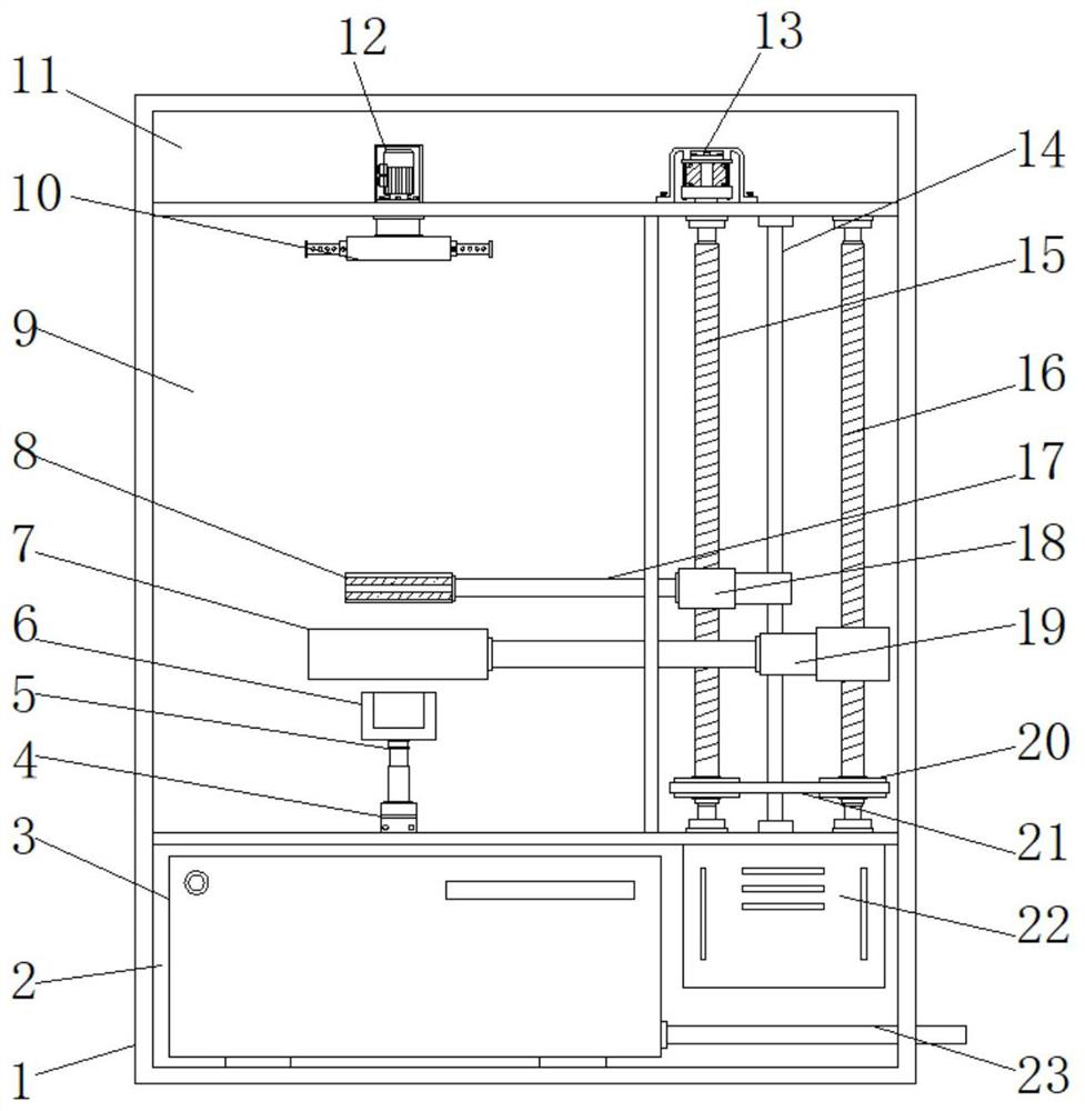
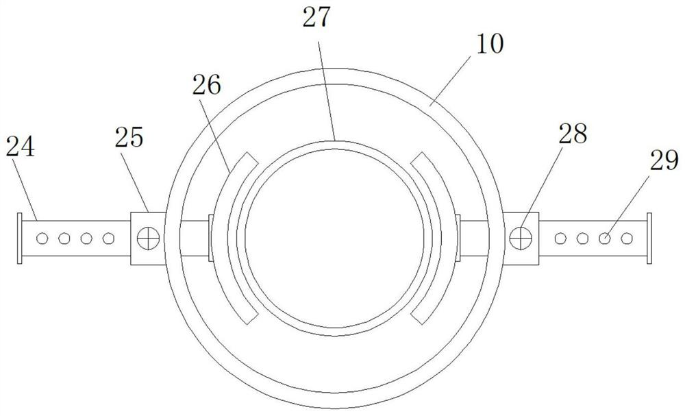
[0021] Example 1: See Figure 1-4 , DSP+ digital high-frequency power supply is equipped with a five-axis linkage quenching machine tool, including a machine tool body 1. The interior of the machine tool body 1 is respectively provided with a first chamber 2, a second chamber 9 and a third chamber 11. The first chamber 2 A water collection box 3 is arranged inside, a cooling ring 7 is arranged inside the second chamber 9, a heating ring 8 is arranged above the cooling ring 7, and a first screw shaft 15 is movably connected to one side inside the second chamber 9 , the outside of the first screw shaft 15 is provided with a first drive block 18, a connecting rod 17 is fixedly connected between the first drive block 18 and the heating ring 8, and a second wire is movably connected to one side of the second chamber 9. The rod shaft 16, the second screw shaft 16 is provided with a second drive block 19, one side of the first chamber 2 is equipped with a numerical control power supp...
Embodiment 2
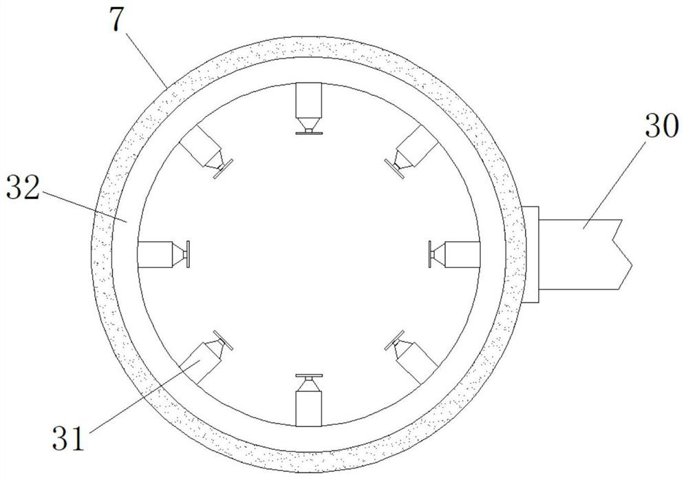
[0024] Embodiment 2: A fixed rod 30 is fixedly connected between the second driving block 19 and the cooling ring 7, and a water delivery pipe 32 is arranged inside the cooling ring 7, and eight groups of high-pressure nozzles 31 are fixedly connected to the inner side of the water delivery pipe 32;
[0025] Specifically, such as figure 1 and image 3 As shown, the second screw shaft 16 drives the cooling ring 7 to move up and down, the parts first pass through the heating ring 8 inside the machine tool to heat them, and then the cooling ring 7 cools them, and the outside of the cooling ring 7 is connected to a water pipe , the water pipe is transported to the inside of the water delivery pipe 32 and sprayed out through the high-pressure nozzle 31, and the cold water cools and quenches the parts inside the cooling ring 7, and the cooling ring 7 and the heating ring 8 move synchronously, closely following the heating ring 8, to realize Quenching immediately after heating impro...
Embodiment 3
[0026] Embodiment 3: The inside of the third chamber 11 is equipped with a second driving motor 13, the output end of the second driving motor 13 is fixedly connected with the top end of the first screw shaft 15 through a coupling, and the inside of the second chamber 9 Fixedly connected to the limit shaft 14, the first drive block 18 and the second drive block 19 are sleeved on the outside of the limit shaft 14, the outside of the first screw shaft 15 is fixedly connected with the driving wheel 33, the second screw shaft 16 A driven wheel 20 is fixedly connected to the outside, and a crawler belt 21 is arranged between the driving wheel 33 and the driven wheel 20;
[0027] Specifically, such as figure 1 and Figure 4 As shown, the second drive motor 13 can drive the first screw shaft 15 to rotate, and the driving wheel 33 outside the first screw shaft 15 and the driven wheel 20 outside the second screw shaft 16 are fixedly connected by crawlers 21. After the screw shaft 15 ...
PUM
 Abstract
Description
Claims
Application Information
 - R&D
- Intellectual Property
- Life Sciences
- Materials
- Tech Scout
- Unparalleled Data Quality
- Higher Quality Content
- 60% Fewer Hallucinations
Browse by: Latest US Patents, China's latest patents, Technical Efficacy Thesaurus, Application Domain, Technology Topic, Popular Technical Reports.
© 2025 PatSnap. All rights reserved.Legal|Privacy policy|Modern Slavery Act Transparency Statement|Sitemap|About US| Contact US: help@patsnap.com


