Textile inspection device

An inspection device and textile technology, applied in the field of textile processing, can solve the problems of deviation of detection results, time-consuming and labor-intensive, affecting the normal use of ultraviolet sensors, etc., and achieve the effect of convenient disassembly and processing and stable position

Inactive Publication Date: 2021-12-14
苏州赛文纺织科技有限公司
View PDF0 Cites 0 Cited by
  • Summary
  • Abstract
  • Description
  • Claims
  • Application Information

AI Technical Summary

Problems solved by technology

[0004] First, in the specific detection process, when the ultraviolet irradiation treatment is performed by manual hand-held treatment, for some treatments that require static irradiation, the ultraviolet sensor needs to be placed on a fixed frame, and manual processing is time-consuming and laborious; second, If the external light is strong, it is easy to affect the normal use of the above-mentioned ultraviolet sensor, which will lead to the deviation of the detection results

Method used


Image

  • Textile inspection device
  • Textile inspection device
  • Textile inspection device

Examples


Embodiment 1

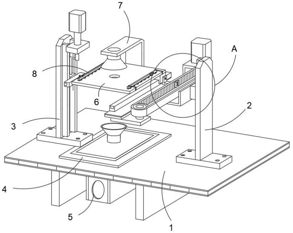
[0035] This embodiment provides the specific structure of the positioning plate on the detection platform, such as figure 1 with 5 As shown, the base plate 1 is equipped with a telescopic cylinder 5 for pulling textiles at its lower end, and a detection platform 6 for placing textiles is provided directly above the base plate 1, and a positioning plate 8 for positioning textiles is arranged on the detection platform 6.

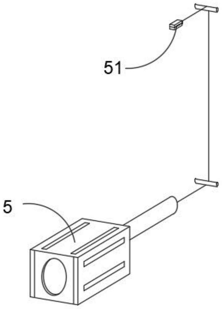
[0036] refer to figure 2 As shown, the end of the output shaft of the telescopic cylinder 5 is fixedly connected with a rope body, and one end of the rope body is connected with a clamp 51, and the clamp 51 is used to be clamped to one side of the textile; the telescopic cylinder 5 is opened to drive the clamp 51 moves backward, and the above-mentioned clamp 51 can adopt a clip or a buckle, only need to ensure that the position of the textile is stable.

[0037] refer to figure 1 with 2 As shown, the base plate 1 and the detection platform 6 are always ke...

Embodiment 2

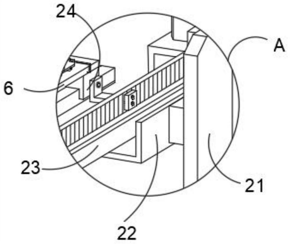
[0042] The present embodiment provides the concrete structure of feeding mechanism, as image 3 As shown, the feeding mechanism 2 is arranged on one side of the upper surface of the bottom plate 1, and the timing belt assembly 23 in the feeding mechanism 2 is used to drive the detection table 6 to move back and forth, and it can be driven when the timing belt assembly 23 rotates. Move back and forth.

[0043] Lifting mechanism 3, which is arranged on the other side of the upper surface of the bottom plate 1, and the lifting mechanism 3 includes a support plate, a No. 1 motor installed on the top of the support plate, and a guide rail frame for connecting the output end of the No. 1 motor and the detection platform 6; Textiles can be laid on the surface of the above-mentioned detection platform 6 .

[0044] refer to image 3 As shown, the feeding mechanism 2 also includes a support plate 21, a lifting plate 22 and a connecting plate group 24. The bottom end of the support pla...

Embodiment 3

[0053] The present embodiment provides the concrete structure of feeding mechanism, as figure 1 As shown, a cover assembly 4 is provided on the upper surface of the bottom plate 1 between the feeding mechanism 2 and the lifting mechanism 3 , and the cover assembly 4 is used to cover the detection light source 7 located below the detection platform 6 .

[0054] refer to Figure 4 As shown, the cover assembly 4 includes a bottom frame 41, an organ cover 42 and a top frame 43,

[0055] The bottom frame 41 is welded on the upper surface of the bottom plate 1, the top frame 43 is embedded in the preset frame groove on the top surface of the bottom frame 41, and is magnetically connected with the bottom frame 41, and the bellows 42 is used to connect the bottom frame 41 and the top frame 43 .

[0056] By adopting the above technical solutions:

[0057] The present invention involves the detection light source 7 above and below the detection table 6, which facilitates comprehensiv...


PUM


Abstract

The invention discloses a textile inspection device. The textile inspection device comprises: a bottom plate, wherein the lower end of the bottom plate is provided with a telescopic cylinder used for pulling a textile, a detection table used for placing the textile is arranged right above the bottom plate, and the detection table is provided with a positioning plate used for positioning the textile; and a feeding mechanism, which is arranged on one side of the upper surface of the bottom plate, wherein a synchronous belt assembly in the feeding mechanism is used for driving the detection table to move front and back. According to technical key points in the invention, a lifting mechanism and the feeding mechanism are combined, so static detection or dynamic detection can be realized, the ultraviolet transmittance of the textile can be obtained, and the ultraviolet-proof performance of the textile can be obtained; through the design of a telescopic cylinder and the positioning plate, positioning and driving treatment of the textile can be completed, and batch automatic detection treatment is achieved; and a micro motor is arranged on the positioning plate, so it is ensured that secondary detection can be conducted on a part of detected areas, and meanwhile, more guarantee is provided for smooth detection operation.

Description

technical field [0001] The invention belongs to the technical field of textile processing, in particular to a textile inspection device. Background technique [0002] Textiles are products made of textile fibers through processing and weaving. China is one of the earliest countries in the world to produce textiles. It is divided into two categories: woven fabrics and knitted fabrics. Industrial textiles are widely used and have many varieties. The common ones are Tarpaulin, gun cover, filter cloth, roadbed cloth, etc.; [0003] When processing textiles, it is usually necessary to detect their quality. Traditionally, ultraviolet sensors are needed to detect and process textiles. The surface of textiles is detected and processed by manually holding the sensor. In specific use, it will appear as follows technical problem: [0004] First, in the specific detection process, when the ultraviolet irradiation treatment is performed by manual hand-held treatment, for some treatment...

Claims


Application Information

Patent Timeline
Patent Type & Authority Applications(China)
IPC IPC(8): G01N21/33G01N21/01
CPCG01N21/33G01N21/01
Inventor 王扬石朦朦
Owner 苏州赛文纺织科技有限公司
Why Eureka
Try Eureka