
Cable laying device for electrical engineering

An electrical engineering and cable technology, applied in the field of cable laying devices for electrical engineering, can solve problems such as poor adjustability, wear of cable skins, affecting the safe use of electrical equipment, etc., to achieve high laying efficiency and avoid cable wear , Improve the effect of the scope of application

Inactive Publication Date: 2021-12-14
ANHUI POLYTECHNIC UNIV MECHANICAL & ELECTRICAL COLLEGE
View PDF0 Cites 0 Cited by
  • Summary
  • Abstract
  • Description
  • Claims
  • Application Information

AI Technical Summary

Problems solved by technology

[0005] The purpose of the present invention is to solve the existing problem that the direct friction between the cable and the surface of the laying device will easily cause the skin of the cable to wear, affect the safe use of subsequent electrical equipment, and have poor adjustability

Method used


Image

  • Cable laying device for electrical engineering
  • Cable laying device for electrical engineering
  • Cable laying device for electrical engineering

Examples


Embodiment Construction

[0036] In order to make the purpose, technical solutions and advantages of the embodiments of the present invention clearer, the technical solutions in the embodiments of the present invention will be clearly and completely described below in conjunction with the accompanying drawings. Apparently, the described embodiments are some, not all, embodiments of the present invention.

[0037] Therefore, the following detailed description of the embodiments of the present invention is not intended to limit the scope of the claimed invention, but merely represents some embodiments of the present invention. Based on the embodiments of the present invention, all other embodiments obtained by persons of ordinary skill in the art without making creative efforts belong to the protection scope of the present invention.

[0038] It should be noted that, in the case of no conflict, the embodiments of the present invention and the features and technical solutions in the embodiments can be com...


PUM


Abstract

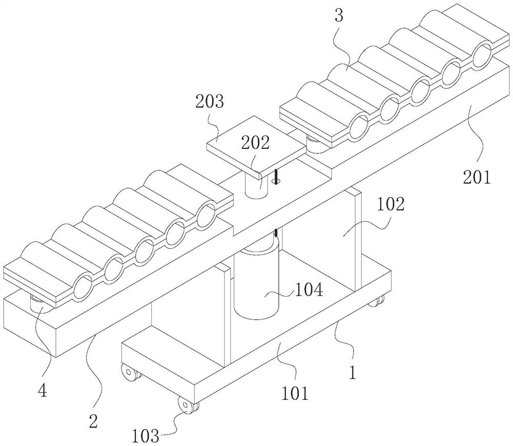
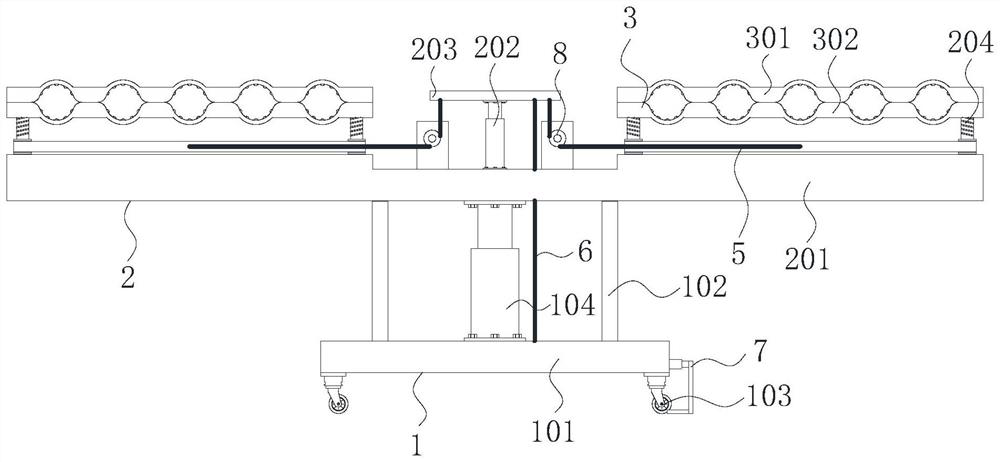
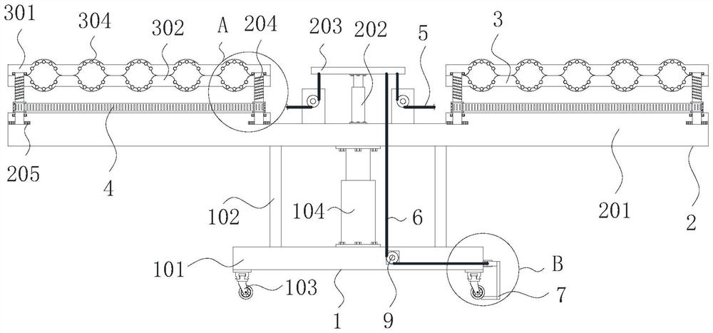
The invention provides a cable laying device for electrical engineering, and the device comprises a supporting assembly, a first traction rope, a second traction rope, a first pulley and a second pulley; a bearing assembly is fixedly mounted above the supporting assembly, a pressing assembly is mounted on the surface of the bearing assembly, a synchronous belt is mounted in the pressing assembly, the surface of the synchronous belt is fixedly connected with a first traction rope, the right front end of the supporting assembly is connected with a limiting assembly, a first pulley is rotationally installed on the surface of the bearing assembly, a second pulley is rotationally installed in the supporting assembly, and the first traction rope is connected with the synchronous belt through the first pulley. According to the device, cable fixing equipment on the left side and the right side can be synchronously adjusted through a traction assembly on the device, so that the device can fix cables of different sizes for use, and a rotatable rubber ball in the device can be matched with a screw telescopic assembly to enable the device to serve as a temporary supporting assembly for use; and the functionality of the device is improved.

Description

technical field [0001] The invention relates to the field of cable laying, in particular to a cable laying device for electrical engineering. Background technique [0002] Electrical engineering is the core project in the field of modern science and technology, covering a wide range. In the process of electrical engineering construction, electrical equipment and wires and cables need to be used for power supply. Connect and install from one place to another. There are still some defects in the use of cable laying devices on the market: [0003] In the process of using the existing cable laying device, it is not convenient for stable installation and laying of cables of different sizes, and it cannot be used in different sizes of laying spaces, and the degree of adjustment is low. , The direct friction between the cable and the surface of the laying device will easily cause the skin of the cable to wear, which will affect the safe use of subsequent electrical equipment. Ther...

Claims


Application Information

Patent Timeline
Patent Type & Authority Applications(China)
IPC IPC(8): H02G1/06
CPCH02G1/06
Inventor 周飞
Owner ANHUI POLYTECHNIC UNIV MECHANICAL & ELECTRICAL COLLEGE
Learn More