Building comprehensive energy-saving management and control system based on environmental protection

A technology of environmental protection and management and control system, applied in the direction of cooling/ventilation/heating transformation, electrical equipment shell/cabinet/drawer, decoration through conduction and heat transfer, etc., can solve the problems of easy damage, misoperation, etc. The effect of falling off and lowering the temperature

Pending Publication Date: 2021-12-14
深圳市宏源建设科技有限公司
View PDF6 Cites 2 Cited by
  • Summary
  • Abstract
  • Description
  • Claims
  • Application Information

AI Technical Summary

Problems solved by technology

[0003] The purpose of the present invention is to provide a comprehensive building energy-saving management and control system based on environmental protection, so as to solve the problem in the above-mentioned background technology that the control panel is always exposed to the outside, which is not only easy to be damaged, but also may cause misoperation

Method used


Image

  • Building comprehensive energy-saving management and control system based on environmental protection
  • Building comprehensive energy-saving management and control system based on environmental protection
  • Building comprehensive energy-saving management and control system based on environmental protection

Examples


Embodiment 1

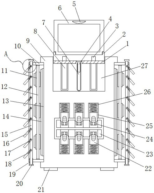
[0027] Example 1: See Figure 1-6 , a building comprehensive energy-saving management and control system based on environmental protection, including a chassis 9 and pillars 21, a set of pillars 21 are fixedly connected to both ends of the bottom of the chassis 9, and a storage slot 27 is embedded in the top of the chassis 9. A group of cooling chambers 10 are fixedly connected to both sides, and one end of the chassis 9 is inlaid with a groove 23;

[0028] The interior of the storage groove 27 is movably connected with the installation groove 2, and the two sides of the two ends of the storage groove 27 are respectively inlaid with a set of limit slide grooves 8, and the interior of the installation groove 2 is articulated with a control panel 6, and the tops of the two ends of the control panel 6 are inlaid respectively. There is a set of pull grooves 5, a set of buffer pads 1 are fixedly connected to both sides of the bottom of the installation groove 2, and a set of limit ...

Embodiment 2

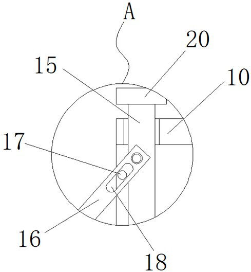
[0032] Embodiment 2: a set of placement grooves 29 are inlaid on both sides of one end of the control panel 6, and the top of the placement groove 29 is hinged with a support plate 28;

[0033] The support plate 28 forms a flexible connection with the placement groove 29, and the width of the support plate 28 is less than the width of the placement groove 29 inside;

[0034] Specifically, such as Figure 4As shown, after the control panel 6 is separated from the inside of the storage groove 27, the support plate 28 at one end of the control panel 6 is extracted from the inside of the placement groove 29, and the bottom end of the placement groove 29 is placed on the top of the cabinet 9, which can realize The control panel 6 is supported to facilitate the operation of the staff;

Embodiment 3

[0035] Embodiment 3: The bottom end of the control panel 6 is fixedly connected with the data line 4, and one end of the receiving groove 27 is inlaid with a through groove 7, the through groove 7 communicates with the inside of the chassis 9, and the data line 4 runs through the installation groove 2 and the through groove 7 And extend to the inside of the chassis 9;

[0036] Specifically, such as figure 1 and Figure 5 As shown, while the control panel 6 is moving, the data line 4 used to connect the control panel 6 to the internal components of the device moves inside the through groove 7, which can protect the data line 4 and prevent the data line from being damaged when the control panel 6 moves. 4 damage;


PUM


Abstract

The invention discloses a building comprehensive energy-saving management and control system based on environmental protection, and the system comprises a case and supporting columns, wherein the two ends of the two sides of the bottom end of the case are fixedly connected with a group of supporting columns. According to the comprehensive energy-saving management and control system for the building based on environmental protection, a buffer pad is arranged, a control panel is pulled to rise through a pull groove, a supporting plate at one end of the control panel is pulled out from the interior of a placement groove, the bottom end of the placement groove is placed at the top end of a case, and the control panel is supported; at the moment, a worker performs management and control through a control panel and energy in the building, after operation is completed, a supporting plate is retracted into a containing groove, the control panel is turned over to be kept perpendicular, then the control panel is pressed downwards to push a mounting groove in the bottom end to descend; the limiting sliding blocks at the two ends of the mounting groove move in the limiting sliding grooves so that the mounting groove and the control panel can be limited, and the problems that the control panel is exposed outside all the time, damage is prone to occurring, and misoperation can occur are solved.

Description

technical field [0001] The invention relates to the technical field of environmental protection, in particular to a building comprehensive energy-saving management and control system based on environmental protection. Background technique [0002] The amount of energy used in our daily life is getting higher and higher, and part of it is wasted in addition to our normal use. This will not only cause economic losses and waste of resources, but also cause pollution. After all, electricity and other energy sources are converted. It will cause pollution, so reducing energy consumption can also reduce environmental pollution. In some buildings, there will be a core energy management and control system to manage the overall energy supply inside the building to reduce energy consumption, but these control systems are in use There are still some defects. The control panel is always exposed to the outside, which is not only vulnerable to damage but also misoperation. The overall inte...

Claims


Application Information

Patent Timeline
Patent Type & Authority Applications(China)
IPC IPC(8): H05K5/02H05K7/20
CPCH05K5/0217H05K5/0247H05K7/20136H05K7/2039
Inventor 陈郅颖赖广文王静山徐建新蒋冬
Owner 深圳市宏源建设科技有限公司
Why Eureka
Try Eureka