
A device for obstetrics and gynecology

A technology of obstetrics and gynecology and natural delivery, applied in massage auxiliary products, physical therapy, stilts, etc., can solve problems such as backaches that cannot be relieved, pregnant women slipping, and poor position-limiting functions, so as to promote pelvic elasticity and fetal descent. Relieves pain and improves grip

Active Publication Date: 2022-05-27
安阳市第六人民医院
View PDF4 Cites 0 Cited by
  • Summary
  • Abstract
  • Description
  • Claims
  • Application Information

AI Technical Summary

Problems solved by technology

[0004] Since the birthing ball is round, it needs to be fixed on the birthing ball stand. However, in actual use, the current birthing ball stand has a poor limit function, which may easily cause the pregnant woman to slip during exercise, and cannot relieve the pregnancy pain of the pregnant woman. Discomfort caused by low back pain and other discomfort

Method used


Image

  • A device for obstetrics and gynecology
  • A device for obstetrics and gynecology
  • A device for obstetrics and gynecology

Examples


Embodiment 1

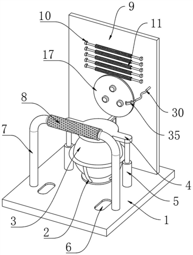
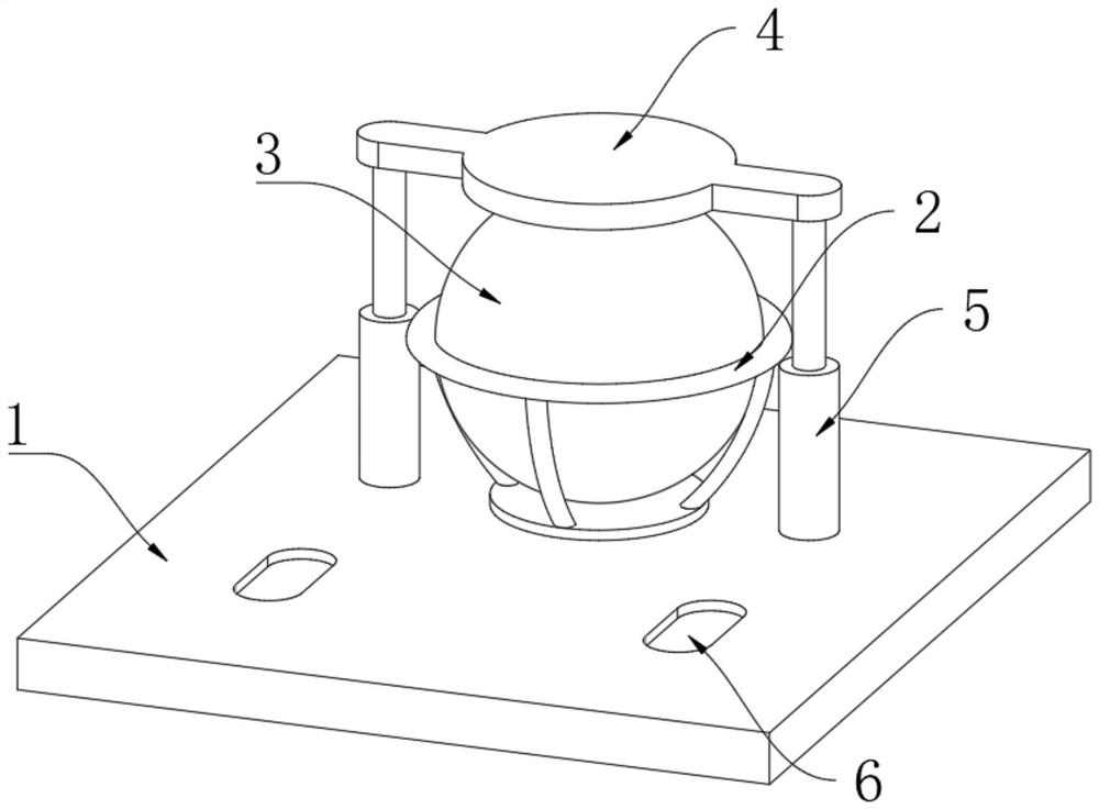
[0030] as Figure 1As shown, an obstetrics and gynecology vaginal midwifery device, comprising mounting the base plate 1, the upper surface of the installation base plate 1 is fixed to install the limit frame 2, the inner wall of the limit frame 2 is placed with a delivery ball 3, the upper surface of the mounting base plate 1 is fixed to the front of the limit frame 2 is fixed to the mounting rack 7, the upper surface of the mounting base plate 1 is relative to the lower position of the friction pad 8 is opened with a limit groove for restricting the movement of the feet 6, and the upper surface of the mounting base plate 1 is fixed on both sides of the relative limit frame 2 is fixedly connected to the telescopic rod 5, The top fixed connection of the two sets of telescopic rods 5 is connected to the seat cushion 4, the upper surface of the mounting base plate 1 is fixed to the rear position of the limit frame 2 is fixed connected to the positioning plate 9, the front left and ri...

Embodiment 2

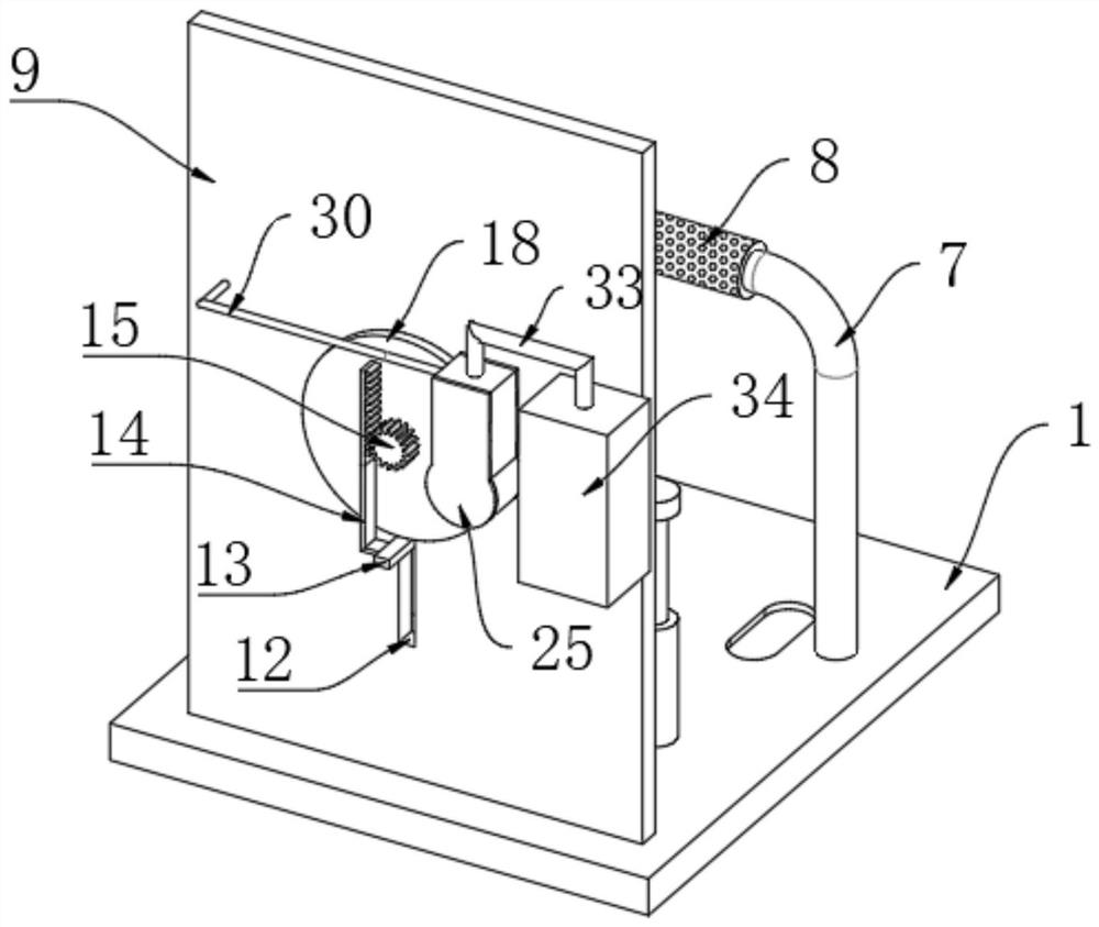
[0042] as Figure 8As shown, on the basis of Example 1, further expansion: the back of the positioning plate 9 is fixed connected to the exhaust housing 25, the inner wall of the suction housing 25 is connected to the eccentric wheel 26, the eccentric position of the eccentric wheel 26 is connected to the activity rod 27, the top activity of the moving rod 27 is connected to the piston plate 25 of the inner wall sliding piston plate 28, the top of the piston plate 28 is fixed to the top of the ejector rod 29, the top of the extraction housing 25 is fixed to connect the finite cylinder 31, The bottom of the limiting cylinder 31 is internally connected to the extraction housing 25, the internal of the limiting cylinder 31 is provided with a sealing ball 32, the top of the limiting cylinder 31 is fixed to the trachea 33, the tracheopus 33 is fixed from one end of the limit cylinder 31 is fixedly connected to the air receiver 34, the exhaust tank 34 is fixedly connected to the back of ...


PUM


Abstract

The invention discloses an obstetrics and gynecology birth aid device, comprising a mounting base plate, a limiting frame is fixedly installed on the upper surface of the mounting base plate, a delivery ball is placed on the inner wall of the limiting frame, and a delivery ball is placed on the upper surface of the mounting base plate A mounting bracket is fixedly connected to the front side of the relative limit frame, and a limit groove for limiting the movement of the feet is provided on the upper surface of the installation base plate relative to the lower position of the friction pad, and the upper surface of the installation base plate is opposite to the position of the limit frame. The left and right sides are fixedly connected with telescopic rods. During pregnancy, using the birthing ball to squat up and down can promote the elasticity of the pregnant woman's pelvis and the descent of the fetus. In the case of the fetus standing upside down, it can also help the rotation of the fetus. At the same time, it can Expand the pelvic space, so it can relieve the labor pain during childbirth, help the baby's fetal head to descend as soon as possible, relieve the pain of pregnant women during labor, and keep pregnant women in a smooth and natural delivery. It has the function of midwifery.

Description

Technical field [0001] The present invention relates to the field of obstetrics and gynecology midwifery technology, specifically a kind of obstetrics and gynecology smooth delivery midwifery device. Background [0002] Before the mother is about to give birth, there may be a period of contraction strengthening, the uterine opening is large, but there is no significant improvement in the decline of the fetal head, you can choose to let the mother sit on the birth ball, which is conducive to the decline of the fetal head. [0003] Ball delivery is aerobic exercise, which can move the mother's body, improve breathing, circulation, coordinate pelvic floor muscle ligaments, reduce pelvic floor discomfort, shorten the course of labor, improve the rate of vaginal delivery, and have a midwifery function. [0004] Because the birth ball is round, it needs to be fixed on the delivery ball rack, but today's delivery ball rack has a poor limit function in actual use, which can easily lead t...

Claims


Application Information

Patent Timeline
Patent Type & Authority Patents(China)
IPC IPC(8): A63B41/00A63B26/00A61H15/00A61M16/00
CPCA63B41/125A63B26/00A61H15/00A61M16/00A61M16/0461A61H2015/0014A61H2015/0028A61H2205/081
Inventor 杜丽娟刘雅宁
Owner 安阳市第六人民医院
Learn More