A high-efficiency dispensing method for power management chips

A power management chip and high-efficiency technology, which is applied to the device and coating of the surface coating liquid, can solve the problems of inability to realize dispensing, low dispensing efficiency, and increase the occupied area, so as to achieve accurate and efficient dispensing work , It is convenient for dispensing processing and ensures the effect of stable transmission

Active Publication Date: 2022-02-08
HENAN XINRUI ELECTRONICS TECH
View PDF8 Cites 0 Cited by
  • Summary
  • Abstract
  • Description
  • Claims
  • Application Information

AI Technical Summary

Problems solved by technology

[0003] Existing dispensing devices for chips on PCBs still have many deficiencies in use, and usually chips are prone to occur during the process of transferring chips on the conveyor belt Shaking, the chip needs to be repositioned after the transfer, and then the glue can be dispensed, resulting in a very low dispensing efficiency. In addition, the existing dispensing device needs to move the chip to a specific position through the transmission belt. The chip is removed from the conveyor belt and then dispensed. Glue cannot be dispensed during the transfer process. This requires a very large size of the workbench, which increases the floor space, and the conveyor belt can only transfer chips of a fixed size. Poor performance, and the dispensing nozzle on the existing dispensing device can only dispensing and fixing the chip on the PCB board with the same thickness and area, poor adaptability, and the parts on the dispensing device can adjust the range of movement Small, poor flexibility of use
[0004] Chinese utility model patent with publication number CN213727485U, although it can realize dispensing on the conveyor belt, but in the process of dispensing, the conveyor belt needs to stop running, etc. The workpiece can only be transferred after dispensing, and the conveyor belt can not be kept working during the dispensing process, which seriously affects the processing efficiency

Method used


Image

  • A high-efficiency dispensing method for power management chips
  • A high-efficiency dispensing method for power management chips
  • A high-efficiency dispensing method for power management chips

Examples


Embodiment Construction

[0032] The specific implementation manners of the present invention will be further described in detail below in conjunction with the accompanying drawings and embodiments. The following examples are only used to illustrate the present invention, but can not be used to limit the scope of the present invention.

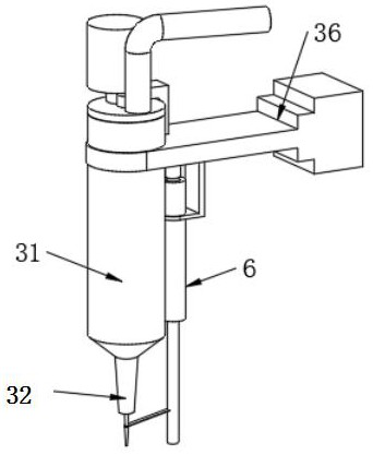
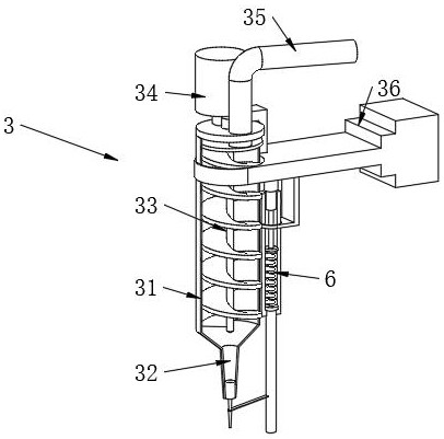
[0033] like figure 1 , figure 2, Figure 5 , Figure 7 , Figure 8 As shown, this embodiment proposes a high-efficiency dispensing device for power management chips, including a base 1, a guide frame 2 is installed above the base 1, a dispensing mechanism 3 is installed in the middle of the guide frame 2, and the dispensing mechanism 3 The first support frame 36 is installed inside the guide frame 2, and the bottom of the first support frame 36 is connected with a glue delivery mechanism 6, and a symmetrically installed transmission mechanism 4 is arranged above the base 1, and a positioning mechanism is connected to the transmission mechanism 4. 5. After the chi...


PUM


Abstract

The invention relates to a high-efficiency dispensing device and a dispensing method for power management chips, which belong to the technical field of dispensing processing. The invention provides a high-efficiency dispensing device and a dispensing method for power management chips, including a base , a guide frame is installed above the base, a dispensing mechanism is installed in the middle of the guide frame, and the glue dispensing mechanism is installed inside the guide frame through the first support frame. A transmission mechanism is installed in the upper middle of the base, and the transmission mechanism is a strip-shaped transmission device installed symmetrically on both sides of the base, and the first electric push rod drives the conveyor belt and the second motor to move in the middle of the base, changing the two The transmission width between the transmission mechanisms facilitates the transmission of chips of different widths, which facilitates the improvement of the transmission efficiency of the device, and protects the edges through the positioning mechanism on the transmission mechanism to avoid deviation of the chips during transmission and ensure that the chips The stable transmission is convenient for accurate and efficient dispensing work.

Description

technical field [0001] The invention relates to a high-efficiency glue dispensing device and a glue dispensing method for power management chips, belonging to the technical field of glue dispensing processing. Background technique [0002] Before the chip on the PCB board is soldered, a dispensing device is required to fix the position of the chip on the PCB board by dispensing glue to ensure that the position of the chip on the PCB board is more accurate and firm when it is welded, and to make the chip and PCB The fit of the board is better. [0003] The existing dispensing devices for chips on PCBs still have many deficiencies in use. Usually, the chips are prone to shaking during the transmission process on the conveyor belt, and the chips need to be repositioned after the transmission is completed. Glue dispensing leads to low dispensing efficiency. In addition, the existing dispensing devices need to move the chip to a specific position through the conveyor belt, then ...

Claims


Application Information

Patent Timeline
Patent Type & Authority Patents(China)
IPC IPC(8): B05C5/02B05C13/02B05C5/00B05C11/10B05D1/26
CPCB05C5/0208B05C13/02B05C5/001B05C5/0225B05C11/1042B05D1/26Y02P70/10
Inventor 陈福操
Owner HENAN XINRUI ELECTRONICS TECH
Why Eureka
Try Eureka