
Outlet structure of solid particle container and solid particle container

A technology of outlet structure and solid particles, applied in bottle/container caps, capping containers tightly with caps, liquid handling, etc., can solve problems such as easy leakage, residual adhesion, and difficulty in controlling the amount of pouring, so as to achieve the goal of not easy to spill Leakage, good sealing, and accurate control of pouring volume

Active Publication Date: 2021-12-17
GUANGZHOU BLUE MOON IND
View PDF6 Cites 0 Cited by
  • Summary
  • Abstract
  • Description
  • Claims
  • Application Information

AI Technical Summary

Problems solved by technology

[0004] The present invention aims to overcome at least one defect (deficiency) of the above-mentioned prior art, and provides an outlet structure of a solid particle container and a solid particle container for solving The existing solid particle containers have problems such as easy leakage, difficult control of pouring volume, and residual adhesion.

Method used


Image

  • Outlet structure of solid particle container and solid particle container
  • Outlet structure of solid particle container and solid particle container
  • Outlet structure of solid particle container and solid particle container

Examples


Embodiment 1

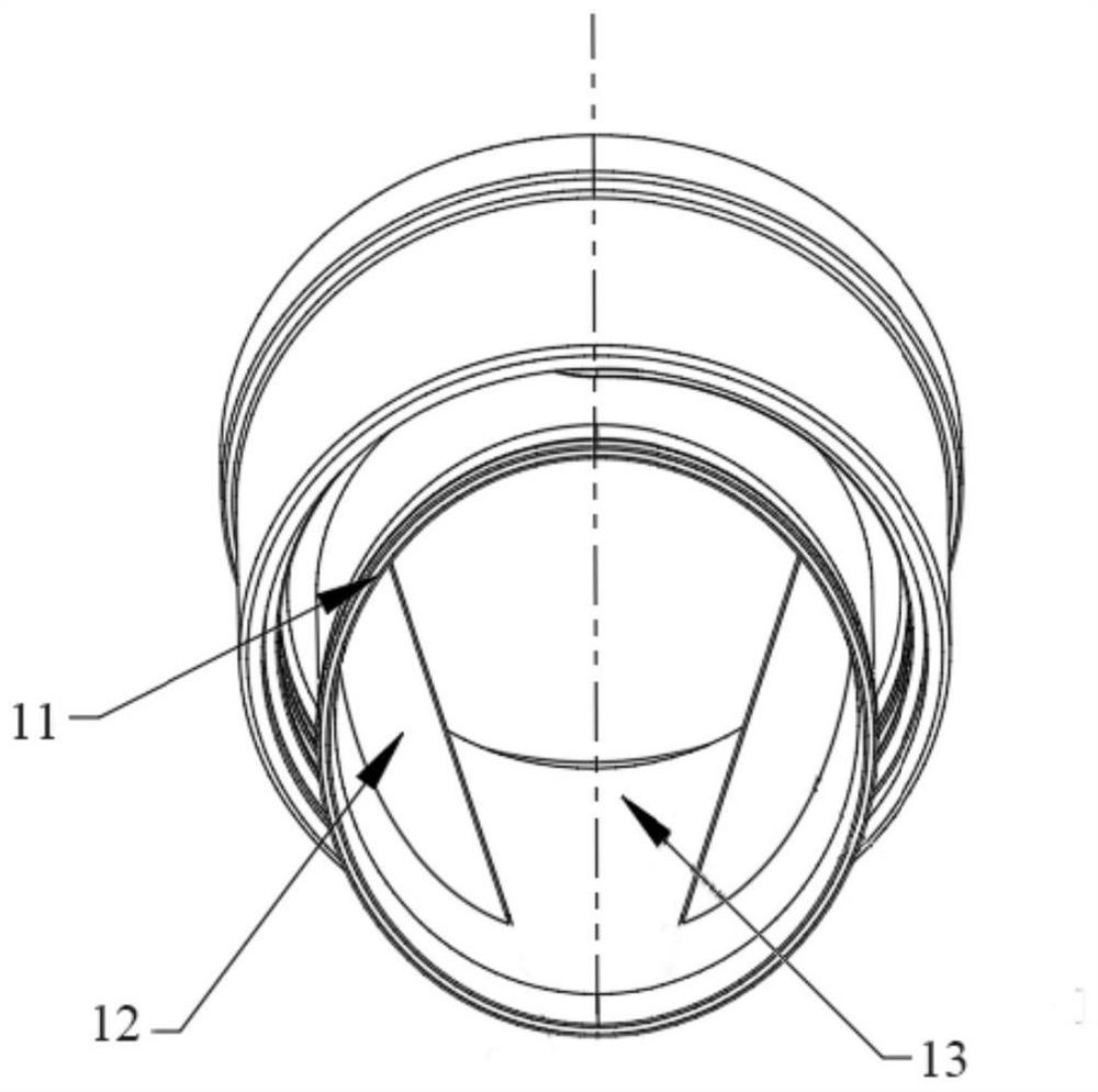
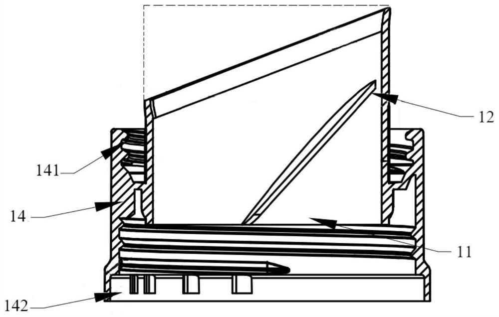
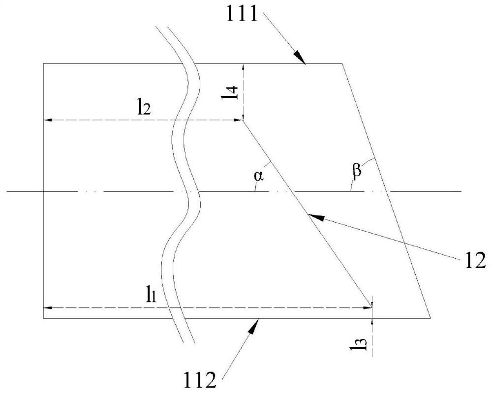
[0038] Such as Figure 1~4 As shown, the present embodiment provides an outlet structure of a solid particle container, including a discharge channel 11 and two guide baffles 12; the discharge channel 11 is cylindrical; two guide baffles 12 are located in the discharge channel 11, near the outlet end of the discharge channel 11, the diameter of the discharge channel 11 is symmetrically distributed on the axis of symmetry, and the discharge port 13 of the discharge channel 11 is formed between the two guide baffles 12; the guide baffle 12 is inclined from the outlet end to the inlet end, forming an included angle α with the main axis of the discharge channel 11; there is a distance l 1 , there is a distance l from the channel lower edge 112 of the discharge channel 11 3 There is a distance l between the far end of the diversion baffle plate 12 and the end face of the inlet end of the discharge channel 11 away from the outlet end 2 , there is a distance l from the upper edge 1...

Embodiment 2

[0051] Such as Figure 5-7 As shown, the present embodiment provides a container for solid particles and a method for using the same. The container includes a chamber 20, a seal 30 and an outlet structure as described in Embodiment 1; the outlet structure 10 is connected to the chamber 20, so that The solid particles stored in the cavity 20 are poured out through the container outlet structure 10; the sealing member 30 is used to seal the outlet structure 10; the lower edge of the discharge port 13 is on the same side as the pouring direction of the container.

[0052] Specifically, the connection between the cavity 20 and the outlet structure 10 is provided with an outer seat 14; the outer seat 14 surrounds the outer wall of the discharge channel 11, and a first matching position 141 is provided between the outer seat 14 and the outer wall; the first matching The position 141 is used to install or disassemble the seal 30 ; the bottom of the outer seat 14 is provided with a se...


PUM


Abstract

The invention relates to the field of novel containers, and provides an outlet structure of a solid particle container and the solid particle container. The outlet structure of the solid particle container comprises a cylindrical discharging channel, and the discharging channel comprises an inlet end, an outlet end and a main shaft. The outlet structure further comprises two flow guide baffles. The two flow guide baffles are arranged in the discharging channel, are symmetrically distributed by taking the diameter of the discharging channel as a symmetry axis, and are connected with the inner side wall of the discharging channel. The flow guide baffles are inclined from the outlet end to the inlet end to form a discharging port inclined relative to the main shaft of the discharging channel. The width D of an opening in the side, close to the inlet end, of the discharging port is larger than the width d of an opening in the side, close to the outlet end, of the discharging port. According to the outlet structure, solid particles smoothly and intensively flow out when dumped out, meanwhile, the solid particles are prevented from being accumulated and remained when dumped back, and a user can flexibly and accurately measure solid particles easily.

Description

technical field [0001] The invention relates to the field of novel containers, more specifically, to an outlet structure of a solid particle container and the solid particle container. Background technique [0002] There are many kinds of solid particles that come into contact with in daily life. Different from liquids, solid particles are more dispersed, and are more likely to leak during the process of pouring out and pouring back into the container, and are easy to absorb moisture to form agglomerates and adhere to the container. , which is one of the important issues that need to be considered in the packaging design; among them, in the cleaning and care products, including bleaching powder, dishwashing powder, laundry fragrance beads, etc., these products usually need to be poured out quantitatively, and the control of pouring volume is also a key issue . [0003] The traditional packaging form of box and spoon needs to keep hands clean and dry, and the solid particles...

Claims


Application Information

Patent Timeline
Patent Type & Authority Applications(China)
IPC IPC(8): B65D83/06B65D41/04B65D25/52B65D53/00
CPCB65D83/06B65D41/04B65D25/52B65D53/00
Inventor 赖展球凌勇
Owner GUANGZHOU BLUE MOON IND
Learn More