
Shooting method of elements

A shooting method and component technology, which is applied in image data processing, instrumentation, computing, etc., can solve the problems of complex calibration process of image edge and center distortion, difficult to complete high-precision placement of large-size components, and increased volume of working head, etc. Achieve the effects of small recognition range, accurate judgment and correction, and precise shooting

Active Publication Date: 2021-12-17
苏州市路远智能装备有限公司
View PDF6 Cites 0 Cited by
  • Summary
  • Abstract
  • Description
  • Claims
  • Application Information

AI Technical Summary

Problems solved by technology

Usually, the method of moving objects multiple times by hardware and splicing multiple images by software is used. The former increases the volume of the working head, reduces the space utilization rate, and makes the control process lengthy. It is difficult to complete without motion monitoring and correction. High-precision placement of large-size components; image stitching cannot avoid the loss of accuracy caused by edge pixel errors. In addition, the image edge and center distortion calibration process is complicated

Method used


Image

  • Shooting method of elements
  • Shooting method of elements
  • Shooting method of elements

Examples


Embodiment Construction

[0035] The present invention will be further described below in conjunction with the accompanying drawings and embodiments.

[0036] The idea, specific structure and technical effects of the present invention will be clearly and completely described below in conjunction with the embodiments and accompanying drawings, so as to fully understand the purpose, features and effects of the present invention. Apparently, the described embodiments are only some of the embodiments of the present invention, rather than all of them. Based on the embodiments of the present invention, other embodiments obtained by those skilled in the art without creative efforts belong to The protection scope of the present invention. In addition, all the connection / connection relationships involved in the patent do not simply refer to the direct connection of components, but mean that a better connection structure can be formed by adding or reducing connection accessories according to specific implementat...


PUM


Abstract

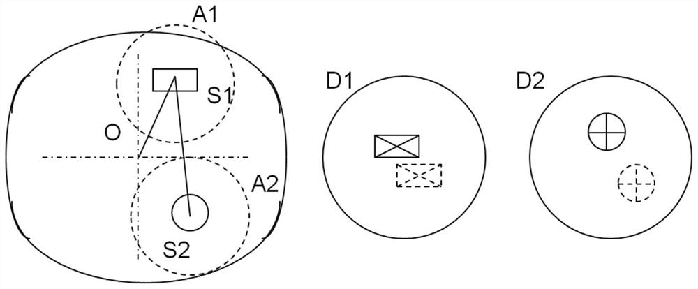
The invention discloses a shooting method of elements, and the method comprises the following steps: S10, shooting a first image: shooting the whole element through a first shooting unit, and obtaining the first image; S20, according to information, different from other regions, of the key feature region of the element, extracting a region containing the information of the key feature region; S30, analyzing the center coordinate S0 of the first image, the center coordinate S1 of the first feature region A1 and the center coordinate S2 of the second feature region A2 according to the first image; S40, determining the movement amount D1 of the element; S50, determining the movement amount D2 of the element; S60, calculating the offset of the element; S70, correcting the position of the suction nozzle according to the offset of the element; the method has the beneficial effects that the element is identified, and the position of the element is accurately judged and corrected.

Description

technical field [0001] The present invention relates to the technical field of component installation, and more specifically, the present invention relates to a method for photographing components. Background technique [0002] The placement machine can only recognize objects in a limited size range, and it is difficult to meet high-precision placement for components larger than the predetermined size. Usually, the method of moving objects multiple times by hardware and splicing multiple images by software is used. The former increases the volume of the working head, reduces the space utilization rate, and makes the control process lengthy. It is difficult to complete without motion monitoring and correction. High-precision placement of large-size components; image stitching cannot avoid the loss of accuracy caused by edge pixel errors. In addition, the image edge and center distortion calibration process is complicated. Contents of the invention [0003] In order to over...

Claims


Application Information

Patent Timeline
Patent Type & Authority Applications(China)
IPC IPC(8): G06T7/60G06T7/73G06T7/13G06T7/00
CPCG06T7/60G06T7/73G06T7/13G06T7/97G06T2207/30164
Inventor 张利杨帮合邓泽峰付文定谢瑞涛
Owner 苏州市路远智能装备有限公司
Features
  • Generate Ideas
  • Intellectual Property
  • Life Sciences
  • Materials
  • Tech Scout
  • Unparalleled Data Quality
  • Higher Quality Content
  • 60% Fewer Hallucinations
Learn More