
Coaxial helicopter and flexible variable-pitch rotor wing

A technology of coaxial helicopters and helicopters, which is applied in the direction of rotorcraft, motor vehicles, aircraft, etc., can solve the problems of increasing the height of the rotor control system, increasing the aerodynamic resistance and weight of the rotor, and severe vibration, so as to improve the safety factor and stability. Reduced aerodynamic induced loss, vibration and noise reduction

Pending Publication Date: 2021-12-21
范家铭
View PDF0 Cites 3 Cited by
  • Summary
  • Abstract
  • Description
  • Claims
  • Application Information

AI Technical Summary

Problems solved by technology

However, the height of the rotor control system is increased, the structure is complex, and the aerodynamic resistance and weight of the rotor are increased, the overall height of the helicopter is increased, the rigidity of the rotor drive shaft is high, and problems such as mechanical fatigue are prone to occur.
[0004] (2) The distance between the upper and lower rotor discs of the rotor is too small, the upper and lower rotor blades will collide, and the aerodynamic induction loss in the blade end area will increase, the vibration will be severe, and the noise will be huge
[0005] (3) The aerodynamic layout and body structure of the helicopter body are complex, the weight is relatively large, the maneuverability and cruising speed cannot be further improved, and it is not suitable for taking off and landing in small spaces such as ship decks

Method used


Image

  • Coaxial helicopter and flexible variable-pitch rotor wing
  • Coaxial helicopter and flexible variable-pitch rotor wing
  • Coaxial helicopter and flexible variable-pitch rotor wing

Examples


Embodiment Construction

[0044] Embodiments of the technical solutions of the present application will be described in detail below in conjunction with the accompanying drawings. The following examples are only used to illustrate the technical solutions of the present application more clearly, and therefore are only examples, rather than limiting the protection scope of the present application.

[0045] It should be noted that, unless otherwise specified, technical terms or scientific terms used in this application shall have the usual meanings understood by those skilled in the art to which this application belongs.

[0046] In the description of the present application, it should be understood that the terms "center", "longitudinal", "transverse", "length", "width", "thickness", "upper", "lower", "front", " Back", "Left", "Right", "Vertical", "Horizontal", "Top", "Bottom", "Inner", "Outer", "Clockwise", "Counterclockwise", "Axial", The orientation or positional relationship indicated by "radial", "...


PUM


Abstract

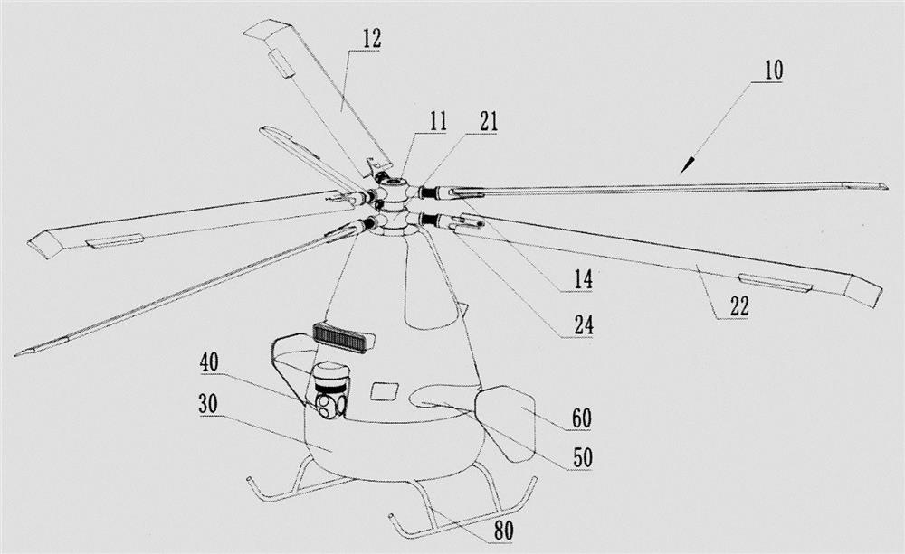
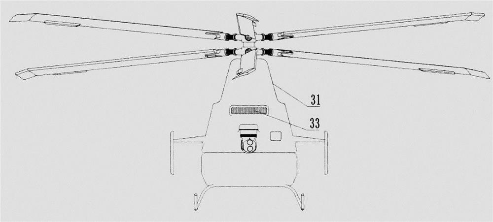
The invention provides a coaxial helicopter and a flexible variable-pitch rotor system. The coaxial helicopter comprises a helicopter body, an upper rotor assembly and a lower rotor assembly; the overall shape of the helicopter body is drop-shaped, and the outer contour of any cross section of the helicopter body is one of a circle, a long circle or an oval; a first blade of the upper rotor assembly is tilted upwards and connected with a first blade clamp assembly, the first blade clamp assembly is rotatably installed at one end of a first variable-pitch journal, and the first variable-pitch journal is fixed to a first blade hub; and a second blade of the lower rotor assembly tilts downwards and is connected with a second blade clamp assembly, the second blade clamp assembly is rotatably installed at one end of a second variable-pitch journal, and the second variable-pitch journal is fixed to a second blade hub. According to the coaxial helicopter, through the design that the helicopter body is in a water drop shape, the structure is simple and compact, the first blade deviates upwards, the second blade deviates downwards, the phenomenon that the first blade and the second blade are subjected to a paddle beating accident when the helicopter flies in a high-speed maneuvering mode is avoided, and the operation stability and safety are high.

Description

technical field [0001] The present application relates to the technical field of coaxial helicopters, in particular to a coaxial helicopter and a flexible variable-pitch rotor. Background technique [0002] In the field of conventional helicopter design, the coaxial dual-rotor helicopter adopts the coaxial anti-propeller design. The design of the aerodynamic layout of the helicopter body and the safe paddle disc spacing of the upper and lower rotors affect the aerodynamic characteristics of the coaxial helicopter and avoid the occurrence of blades. Important parameters for crash accidents. Although existing technical solutions can satisfy the basic functions of helicopter flight, they have the following deficiencies: [0003] (1) The larger the distance between the upper and lower blades of the rotor, the smaller the induced loss, which can avoid collision accidents between the upper and lower rotor blades. However, the height of the rotor control system is increased, the ...

Claims


Application Information

Patent Timeline
Patent Type & Authority Applications(China)
IPC IPC(8): B64C27/10B64C27/32
CPCB64C27/10B64C27/322
Inventor 范家铭
Owner 范家铭
Learn More