Pull rod device used for steel tapping machine and assembling method of pull rod device

A tie rod device and assembly method technology, applied in furnaces, heat treatment equipment, heat treatment furnaces, etc., can solve the problems of thread length limitation, accelerated tapping rhythm, difficult manufacturing, etc., to increase overall strength, avoid breakage, and improve connection stability. sexual effect

Active Publication Date: 2021-12-21
新余钢铁股份有限公司
View PDF17 Cites 0 Cited by
  • Summary
  • Abstract
  • Description
  • Claims
  • Application Information

AI Technical Summary

Problems solved by technology

[0003] Since the tapping machine has been in the transitional space between 1100°C inside the furnace and room temperature outside the furnace for a long time, the width and weight of the slab lifted by the tapping arm change frequently, so that the pull rod device of the tapping machine is in the state of frequent tension and compression alternating stress Under the action, the tie rod parts are very prone to fatigue damage; at the same time, in the general connection method of adjusting the structure of the screw nut, there is a point of minimum structural strength at the undercut groove at the end of the thread on the screw rod. Breakage often occurs, causing major accidents where slabs fall into the heating furnace
[0004] Therefore, the conventional heating furnace tapping machine pull rod device has very high requirements on materials, heat treatment and machining technology, and is difficult to manufacture, with a long cycle and the actual service life is difficult to meet the design requirements, resulting in increased output and output of slab heating furnaces. Steel Tempo Acceleration Limited
[0005] The original tie rod device of the tapping machine is easy to break at the thread relief groove of the long-stroke connecting stud and the short-stroke adjusting stud, and the process of adjusting the length of the long-stroke tie rod by rotating the short-stroke adjusting stud and the cylindrical adjusting nut is very difficult. Convenient; restricted by thread length, length adjustment range is limited

Method used


Image

  • Pull rod device used for steel tapping machine and assembling method of pull rod device
  • Pull rod device used for steel tapping machine and assembling method of pull rod device
  • Pull rod device used for steel tapping machine and assembling method of pull rod device

Examples


no. 1 example

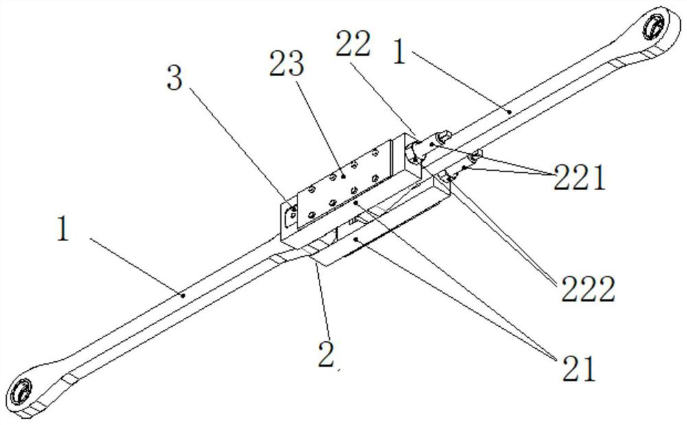
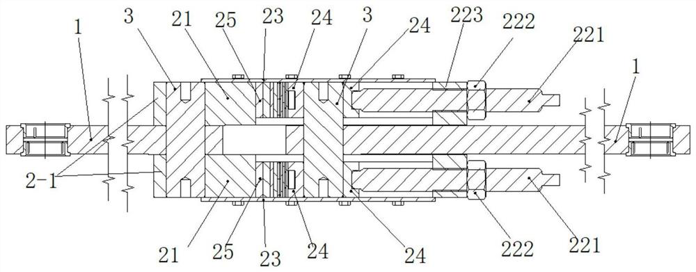
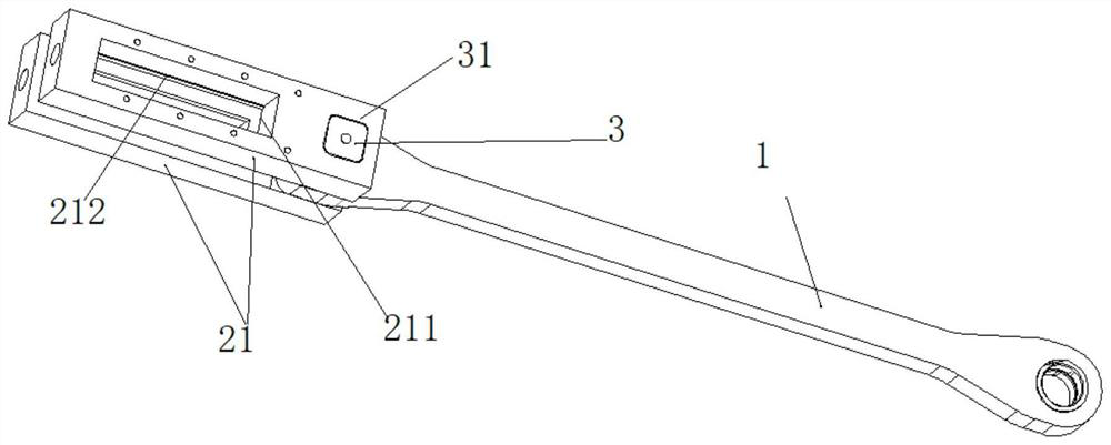
[0056] One end of the square frame plate 2-1 is connected to a bridging long plate 1 through a first connecting portion, and the other end of the square frame plate 2-1 is connected to another bridging long plate 1 through a second connecting portion; this connection method can When the second connecting groove 211 is a strip-shaped groove, the distance between the two bridging long plates 1 can be changed.

no. 2 example

[0058] One end of the square frame plate 2-1 is connected to a bridging long plate 1 through a first connecting portion, and the other end of the square frame plate 2-1 is also connected to another bridging long plate 1 through a first connecting portion; this connection method, The connection between the two bridging long boards 1 and the frame board 2-1 can be realized stably; with such a connection method, the connection between the bridging long board 1 and the square board 2-1 can be simplified, which facilitates the bridging of the long boards 1 assembly connection.

no. 3 example

[0060] One end of the square frame plate 2-1 is connected to a bridging long plate 1 through the second connecting portion, and the other end of the square frame plate 2-1 is also connected to another bridging long plate 1 through the second connecting portion; When the groove 211 is a bar-shaped groove, the present invention adopts such a connection method, which can realize the change of the distance between the two bridging long plates 1; The adjustment range of the tie rod device can be increased.

[0061] Further, in the present invention, the locking mechanism 22 includes a locking bolt 221 and a threaded hole 223 provided at the end of the frame plate 2-1, and the second connecting groove 211 connects with the frame plate through the threaded hole 223 2-1 The outer side is connected; the locking bolt 221 passes through the threaded hole 223 and is connected with the insertion prism 3 in the second connecting groove 211; in actual use, the locking bolt 221 in the locking...


PUM

PropertyMeasurementUnit
thicknessaaaaaaaaaa

Abstract

The invention relates to the field of steel tapping machines, in particular to a pull rod device used for a steel tapping machine and an assembling method of the pull rod device. The pull rod device comprises bridging long plates, and the adjacent bridging long plates are connected through a square frame mechanism; and the square frame mechanism comprises square frame plates, and the adjacent bridging long plates are connected through the square frame plates. The pull rod device used for the steel tapping machine is disclosed. Through cooperation of the bridging long plates and the square frame mechanism, the overall strength of a pull rod can be well improved; and during actual use, the pull rod device can be used for replacing a traditional screw rod type pull rod structure, the disclosed pull rod structure does not use threaded connection, connection is achieved through a plug-in type structure, better connection stability is achieved, and meanwhile the problem that threads are prone to breakage during traditional screw connection is avoided.

Description

technical field [0001] The invention relates to the field of steel tapping machines, in particular to a tie rod device for a steel tapping machine and an assembly method thereof. Background technique [0002] The long-stroke tie rod structure of the conventional heating furnace tapping machine is a rotary joint with cylindrical pin holes and threaded holes distributed at both ends, which are respectively connected with the lifting cylinder and the rotary crank through the cylindrical pins, and the long stroke is connected by a threaded pair in the middle. The stud and the short-stroke adjustment stud are connected with the cylindrical adjustment nut, and the length of the long-stroke pull rod is adjusted. [0003] Since the tapping machine has been in the transitional space between the temperature above 1100°C in the furnace and the room temperature outside the furnace for a long time, the width and weight of the slab lifted by the tapping arm change frequently, so that the ...

Claims


Application Information

Patent Timeline
Patent Type & Authority Applications(China)
IPC IPC(8): C21D9/70
CPCC21D9/70Y02P70/10
Inventor 王晓东王军陈奋宋子鹏钟风清邹秋兰金鹏肖文忠
Owner 新余钢铁股份有限公司
Why Eureka
Try Eureka