
Steel damping shock absorption anti-falling beam support

A technology of steel damping and anti-drop beams, applied in bridges, bridge parts, bridge construction, etc., can solve the problems of fixed pier damage, relative displacement, lack of energy dissipation devices, etc., and achieve the effect of controllable earthquake behavior and reasonable structure

Active Publication Date: 2021-12-21
TONGJI UNIV
View PDF9 Cites 0 Cited by
  • Summary
  • Abstract
  • Description
  • Claims
  • Application Information

AI Technical Summary

Problems solved by technology

[0003] Under the action of earthquake load, since the movable pier has no connection device, there will be a large relative displacement of the pier beam, and most of the seismic force is borne by the fixed pier. Under rare earthquakes, the damage of the fixed pier is more serious, and there is no energy dissipation device. , there may also be a danger of falling beams, and additional anti-falling beam devices need to be installed. The design and construction of anti-falling beam devices in actual projects are relatively cumbersome

Method used


Image

  • Steel damping shock absorption anti-falling beam support
  • Steel damping shock absorption anti-falling beam support
  • Steel damping shock absorption anti-falling beam support

Examples


Embodiment 1

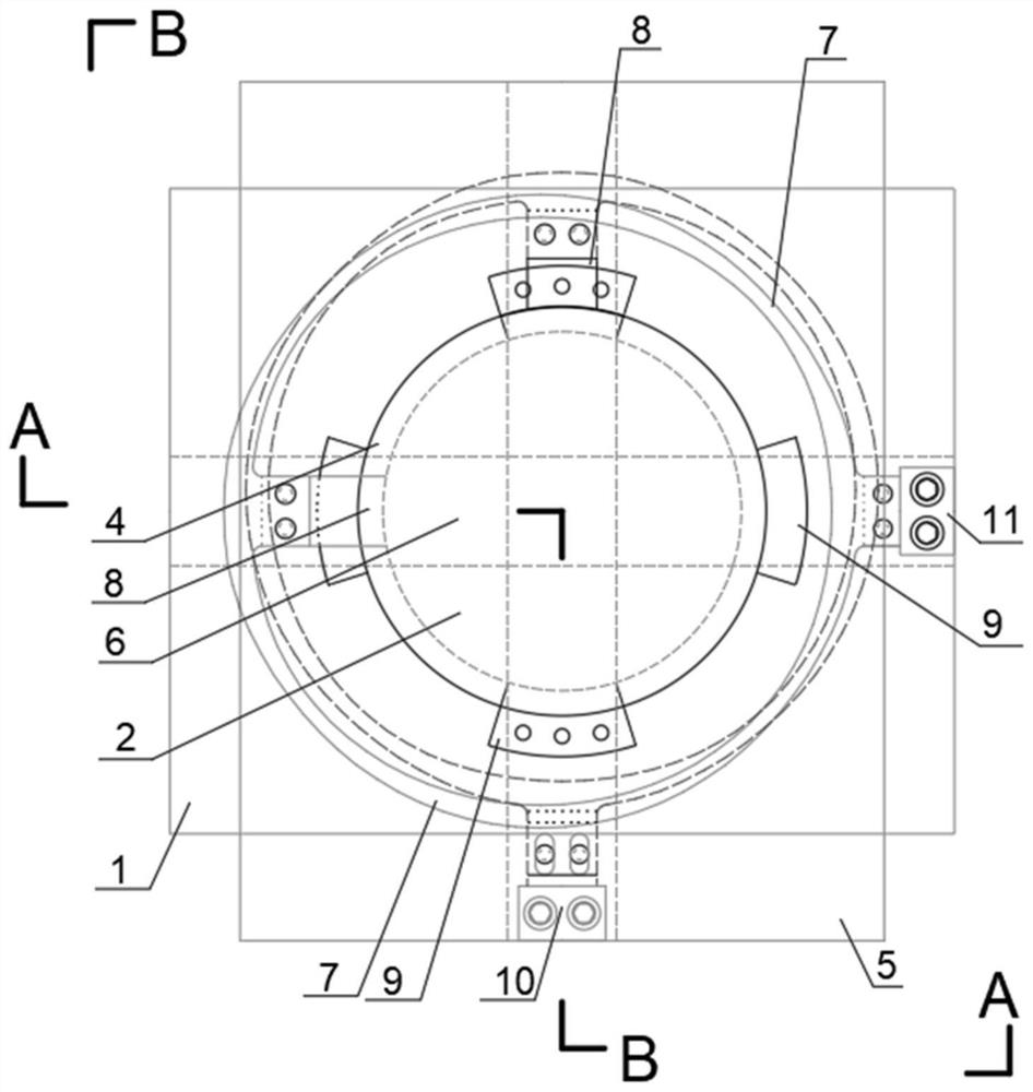
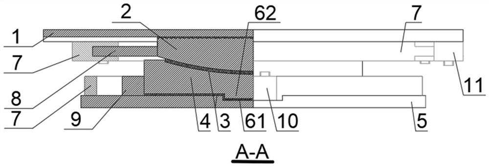
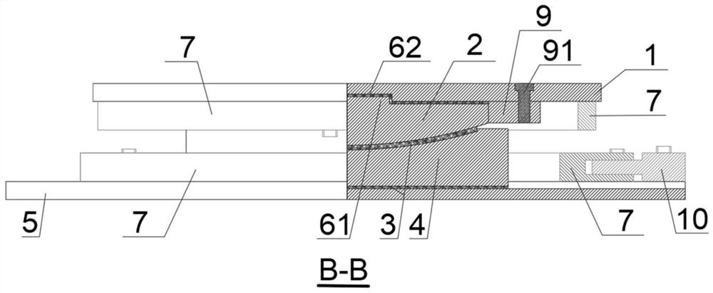
[0069] Based on the above implementation methods, this embodiment provides a one-way movable steel damping and anti-drop beam support, such as figure 1 , figure 2 , image 3 , Figure 4 , Figure 5 , Figure 6 and Figure 7 As shown, the support mainly includes an upper seat plate 1, a spherical crown 2, a middle seat plate 4 and a lower seat plate 5, between the upper seat plate 1 and the spherical crown 2, between the spherical crown 2 and the middle seat plate 4, and the middle seat plate 4 and the lower seat plate 5 are provided with a sliding friction pair 3, between the upper seat plate 1 and the spherical crown 2, between the middle seat plate 4 and the lower seat plate 5 are provided with a directional slideway 6 and an annular steel damping element 7 .

[0070] The directional slideway 6 between the upper seat plate 1 and the ball cap 2 is composed of a chute 62 and a slide rail 61, the slide rail 61 is connected with the ball cap 2 as a whole, the chute 62 is ...

Embodiment 2

[0075] Such as Figure 9 , Figure 10 and Figure 11 As shown, a fixed-shaped steel damping and anti-drop beam support mainly includes an upper seat plate 1, a spherical crown 2, a middle seat plate 4 and a lower seat plate 5, between the upper seat plate 1 and the spherical crown 2, the ball Sliding friction pairs 3 are provided between the crown 2 and the middle seat plate 4, between the middle seat plate 4 and the lower seat plate 5, between the upper seat plate 1 and the ball crown 2, and between the middle seat plate 4 and the lower seat plate 5 Orientation slideway 6 and annular steel damping element 7 are all provided.

[0076] The directional slideway 6 between the upper seat plate 1 and the ball cap 2 is composed of a chute 62 and a slide rail 61, the slide rail 61 is connected with the ball cap 2 as a whole, the chute 62 is located on the upper seat plate 1, and the slide rail 61 and the chute 62 is provided with a sliding friction pair 3; the direction of the dir...

Embodiment 3

[0081] Such as Figure 11 , Figure 12 and Figure 13 As shown, a two-way movable steel damping, shock absorption and anti-fall beam support mainly includes an upper seat plate 1, a spherical crown 2, a middle seat plate 4 and a lower seat plate 5, between the upper seat plate 1 and the spherical crown 2, Sliding friction pairs 3 are provided between the spherical crown 2 and the middle seat plate 4, between the middle seat plate 4 and the lower seat plate 5, between the upper seat plate 1 and the spherical crown 2, and between the middle seat plate 4 and the lower seat plate 5. There are directional slides 6 and annular steel damping elements 7 between them.

[0082]The directional slideway 6 between the upper seat plate 1 and the ball cap 2 is composed of a chute 62 and a slide rail 61, the slide rail 61 is connected with the ball cap 2 as a whole, the chute 62 is located on the upper seat plate 1, and the slide rail 61 and the chute 62 is provided with a sliding friction...


PUM


Abstract

The invention relates to a steel damping shock absorption anti-falling beam support. The beam support comprises an upper support plate, a spherical crown, a middle support plate and a lower support plate, wherein sliding friction pairs are arranged between the upper support plate and the spherical crown, between the spherical crown and the middle support plate and between the middle support plate and the lower support plate, and directional slide ways and annular steel damping elements are arranged between the upper support plate and the spherical crown and between the middle support plate and the lower support plate. Under the normal use condition of a bridge, displacement requirements of the main beam under the load effects of temperature, shrinkage and creep, vehicle braking force and the like can be met; when an earthquake comes, when the shearing force borne by the support exceeds a set capacity value, the pin is cut off, the upper seat plate and the spherical crown or the middle seat plate and the lower seat plate generate translational friction slippage along the slide way, and inertia force generated by the main beam is prevented from being continuously transmitted to the pier; the annular steel damping elements on the supports play a role to dissipate earthquake energy, when the displacement of the pier beam is increased to a certain degree, the annular steel damping elements can make contact with the limiting blocks, the steel damping elements are prevented from continuously deforming to form pull rods, and the beam falling prevention effect is achieved.

Description

technical field [0001] The invention belongs to the technical field of shock-absorbing and isolating components for bridge engineering, and relates to a steel damping, shock-absorbing and anti-drop beam support. Background technique [0002] Bearings are functional components that connect bridge girders and piers. The fixed support can realize the displacement constraint on the main girder under the normal use condition of the bridge; the movable support can satisfy the expansion and contraction of the main girder under the normal use condition. In a simply supported girder bridge, one end of the girder uses a fixed support and the other end uses a movable support; in a continuous girder bridge, only one pier in a link uses a fixed support, and the rest of the piers are arranged with movable supports. [0003] Under the action of earthquake load, since the movable pier has no connection device, there will be a large relative displacement of the pier beam, and most of the se...

Claims


Application Information

Patent Timeline
Patent Type & Authority Applications(China)
IPC IPC(8): E01D19/04E01D19/02
CPCE01D19/048E01D19/02
Inventor 王君杰刘猛
Owner TONGJI UNIV
Learn More