Support for shock absorption and isolation of bridge

A technology of shock absorption and isolation and support, which is applied in the direction of bridges, bridge parts, bridge materials, etc., can solve the problems of beam body rising or falling, unstable friction coefficient, structural conflict, etc., and achieve the effect of preventing damage

Pending Publication Date: 2020-04-07
CENT SOUTH UNIV
View PDF0 Cites 1 Cited by
  • Summary
  • Abstract
  • Description
  • Claims
  • Application Information

AI Technical Summary

Problems solved by technology

[0004] 1. Under normal use conditions, due to the disadvantages of the structure of the support itself, the beam body will be raised and the road surface will be raised, which will affect the driving comfort and safety
Specifically: when the bearing is displaced under normal temperature changes and during operation, it will cause the beam body to rise or fall continuously, affecting driving comfort and safety
[0005] 2. The coefficient of friction is unstable, which affects the effect of shock absorption and isolation
The slide plate of the existing shock-absorbing and isolation bearing adopts the slide plate material

Method used


Image

  • Support for shock absorption and isolation of bridge
  • Support for shock absorption and isolation of bridge
  • Support for shock absorption and isolation of bridge

Examples


Embodiment 1

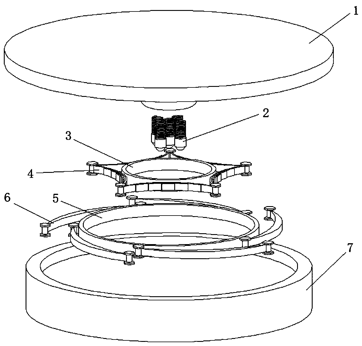
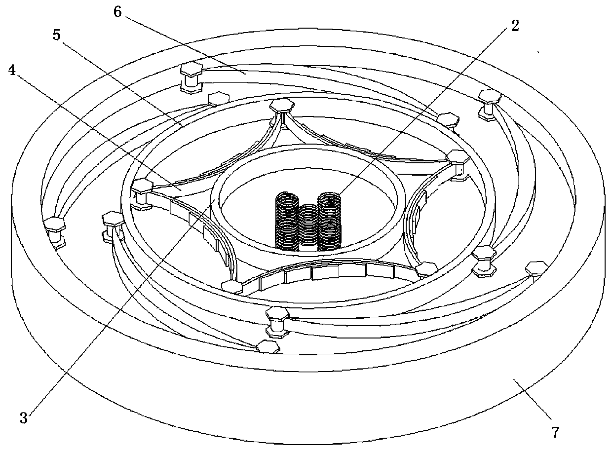
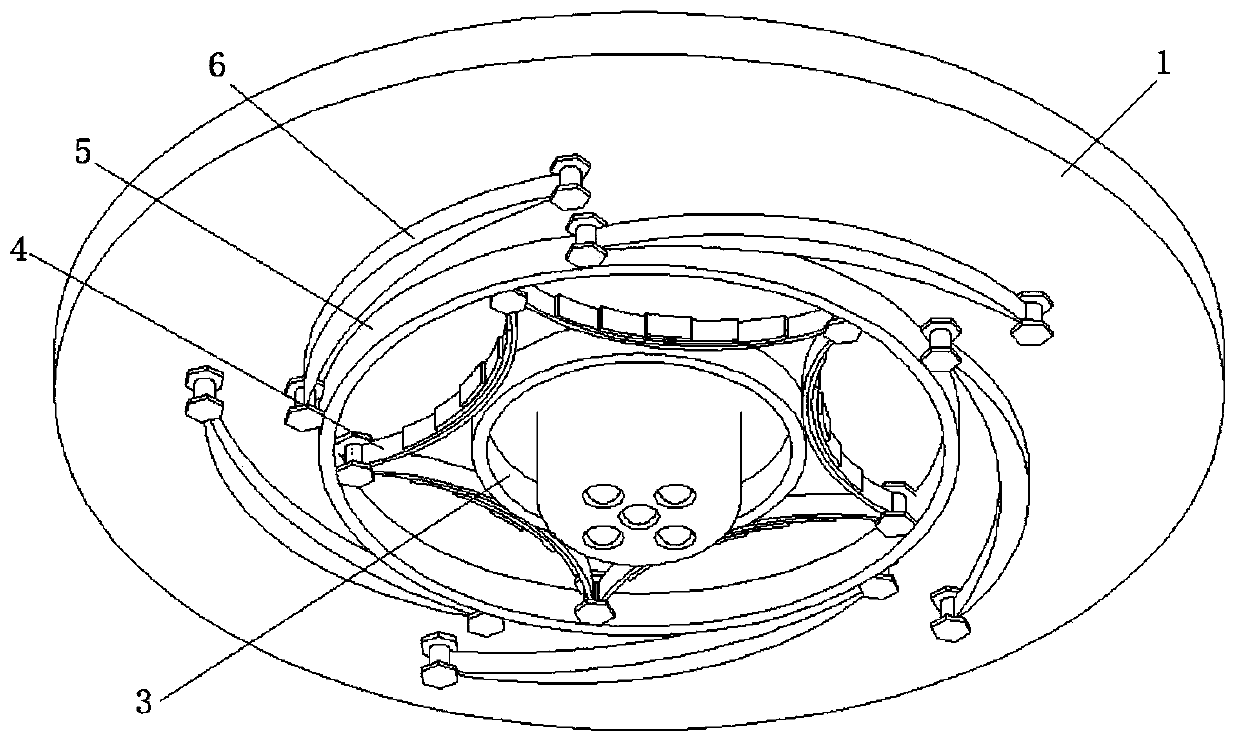
[0037] see Figure 1-7 , a support for shock absorption and isolation of bridges, specifically a shock absorption and isolation support with a limit ring applied to bridges, including an upper seat plate 1, an energy-absorbing assembly, a lower seat plate 7 and at least one set of The elastic component 2, the lower seat plate 7 is provided with a mold cavity, the lower end of the upper seat plate 1 is provided with accommodating cavities equal in number to the elastic components 2, and the elastic components 2 are arranged in each accommodating cavity correspondingly, The upper seat plate 1 is slidably arranged on the bottom surface of the cavity through the elastic component 2, and the energy absorbing component is arranged in the cavity and is located between the lower end of the upper seat plate 1 and the inner wall of the cavity.

[0038] In actual use, the upper seat plate is connected to the bottom surface of the beam body to support the beam body, and the lower seat pla...

Embodiment 2

[0054] The difference between this embodiment and Embodiment 1 is that the energy-absorbing assembly includes an inner limit ring 3 and at least three leaf springs 4, and a plurality of leaf springs 4 are along the outer circumference of the inner limit ring 3. Uniformly arranged, the single plate spring 4 connects the inner wall of the cavity and the outer wall of the inner limiting ring 3 , and the lower end of the upper seat plate 1 is arranged in the inner limiting ring 3 .

[0055] Preferably, the leaf spring is hinged to the inner side wall of the cavity, and is fixedly connected to the inner limiting ring, that is, welded.

[0056] In actual use, the energy-absorbing component can only be equipped with an inner limit ring and a leaf spring to dissipate energy, that is, the method of this embodiment, or an inner limit ring, an outer limit ring, a leaf spring and a damper Energy consumption is the method of Embodiment 1, and the specific setting method should be selected ...


PUM


Abstract

The invention provides a support for shock absorption and isolation of a bridge. The support comprises an upper base plate, an energy absorption assembly, a lower base plate and at least one group ofelastic assemblies, a cavity is formed in the lower base plate; containing cavities with the number equal to that of the elastic assemblies are formed in the lower end of the upper base plate, the elastic assemblies are arranged in the containing cavities in a one-to-one correspondence mode, the upper base plate is arranged on the bottom face of the cavity in a sliding mode through the elastic assemblies, and the energy absorption assemblies are arranged in the cavity and located between the lower end of the upper base plate and the inner side wall of the cavity. By the adoption of the technical scheme, the support has the advantages that earthquake energy can be consumed through deformation, the shock reduction and isolation effect is achieved, and a bridge is prevented from being damaged; and the requirements of translational displacement and rotational displacement in the daily use process are met.

Description

technical field [0001] The invention relates to the technical field of bridge supports, in particular to a support for shock absorption and isolation of bridges. Background technique [0002] Earthquakes are sudden natural disasters. In order to avoid earthquakes causing huge losses to people's lives and properties, at present, engineering structures often take seismic isolation measures to reduce the loss of earthquakes to engineering structures. [0003] There are the following problems in existing similar shock-absorbing and isolating bearings used in bridges: [0004] 1. Under normal use conditions, due to the disadvantages of the structure of the support itself, the beam body will be raised and the road surface will be raised, which will affect the driving comfort and safety. To be specific: when the bearing changes in normal temperature and moves during operation, it will cause the beam body to rise or fall continuously, which will affect the comfort and safety of dri...

Claims


Application Information

Patent Timeline
IPC IPC(8): E01D19/04E01D101/30
CPCE01D19/041E01D2101/30
Inventor 魏标贾晓龙蒋丽忠李姗姗胡章亮汪伟浩
Owner CENT SOUTH UNIV
Why Eureka
Try Eureka