
Multi-direction machining device for machining automobile transmission shaft

A technology for processing equipment and transmission shafts, applied in metal processing equipment, metal processing, metal processing machinery parts, etc., can solve problems such as low work efficiency and long processing time of automobile transmission shafts

Inactive Publication Date: 2021-02-19
黄婷
View PDF4 Cites 0 Cited by
  • Summary
  • Abstract
  • Description
  • Claims
  • Application Information

AI Technical Summary

Problems solved by technology

[0003] At present, the existing processing device used for surface processing of the automobile transmission shaft can only process the plane of the automobile transmission shaft in one direction. After the plane of the automobile transmission shaft in one direction is processed, it takes time to adjust the processing device The position of the upper knife edge or the position of the car transmission shaft, after ensuring that the processing position is correct, the second processing can be performed on the plane in the second direction of the car drive shaft, which will result in a longer processing time for the car drive shaft, resulting in work The efficiency is low, so a solution that can alleviate the above problems is urgently needed

Method used


Image

  • Multi-direction machining device for machining automobile transmission shaft
  • Multi-direction machining device for machining automobile transmission shaft
  • Multi-direction machining device for machining automobile transmission shaft

Examples


Embodiment Construction

[0025] The following description serves to disclose the present invention to enable those skilled in the art to carry out the present invention. The preferred embodiments described below are only examples, and those skilled in the art can devise other obvious variations.

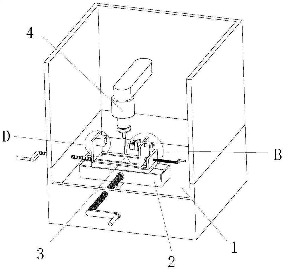
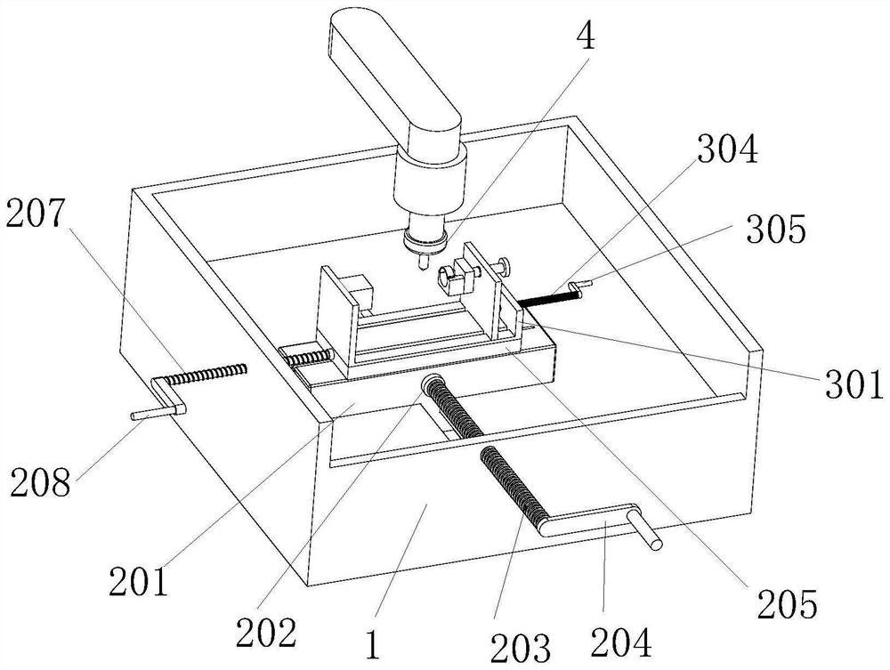
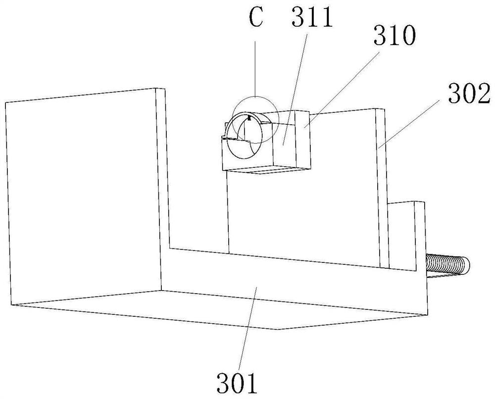
[0026] see Figure 1-8 , an embodiment provided by the present invention: a multi-directional processing equipment for the processing of automobile transmission shafts, including a first base 1, the inner lower end of the first base 1 is provided with a displacement adjustment mechanism 2, and the displacement adjustment mechanism 2 Including a second base 201, a first fixed bearing 202, a first screw 203, a first rotating handle 204, a fixed table 205, a second fixed bearing 206, a second screw 207 and a second rotating handle 208, the first base 1 The inner lower end of the base is provided with a second base 201, the front end of the second base 201 is provided with a first fixed bearing 202, the inner s...


PUM


Abstract

The invention discloses a multi-direction machining device for machining an automobile transmission shaft. The multi-direction machining device comprises a first base table, wherein a displacement adjusting mechanism is arranged at the lower end of the interior of the first base table; the displacement adjusting mechanism comprises a second base table, a first fixing bearing, a first screw rod, afirst rotating handle, a fixing table, a second fixing bearing, a second screw rod and a second rotating handle; the second base table is arranged at the lower end of the interior of the first base table; the first fixing bearing is arranged at the front end of the second base table; the first screw rod is arranged on the inner surface and the front end of the first fixing bearing; the first rotating handle is arranged at the front end of the first screw rod; and the fixing table is arranged at the upper end of the second base table. According to the multi-direction machining device, the structure is stable, the plane position of a product in the machining process can be conveniently and stably adjusted, the purpose of multi-angle machining of the surface of the automobile transmission shaft can be achieved, the working efficiency is improved, and the use requirements are better met.

Description

technical field [0001] The invention relates to the field of automobile parts processing, in particular to a multi-directional processing equipment for processing automobile transmission shafts. Background technique [0002] The car transmission shaft is the shaft that can transmit power in the transmission shaft of the universal transmission device. It is a rotating body with high speed and few supports. Therefore, its dynamic balance is very important. Generally, the transmission shaft must be checked before leaving the factory. Dynamic balance test, and adjusted on the balance machine, for the car with front engine and rear wheel drive, it is the shaft that transmits the rotation of the transmission to the final reducer. Gimbal connection. [0003] At present, the existing processing devices used for surface processing of automobile transmission shafts can only process the plane of the automobile transmission shaft in one direction. The position of the upper knife edge ...

Claims


Application Information

Patent Timeline
IPC IPC(8): B23D79/00B23Q3/04B23Q3/06B23Q7/02
CPCB23D79/00B23Q3/04B23Q3/062B23Q7/02
Inventor 黄婷
Owner 黄婷
Learn More