Physiotherapy device for nursing and treating nerve pain
A pain and nerve technology, which is applied in the field of physiotherapy devices for nerve injury and pain care and treatment, and can solve problems such as inability to contact with water and foot trauma.
- Summary
- Abstract
- Description
- Claims
- Application Information
AI Technical Summary
Problems solved by technology
Method used
Image

Examples
Embodiment 1
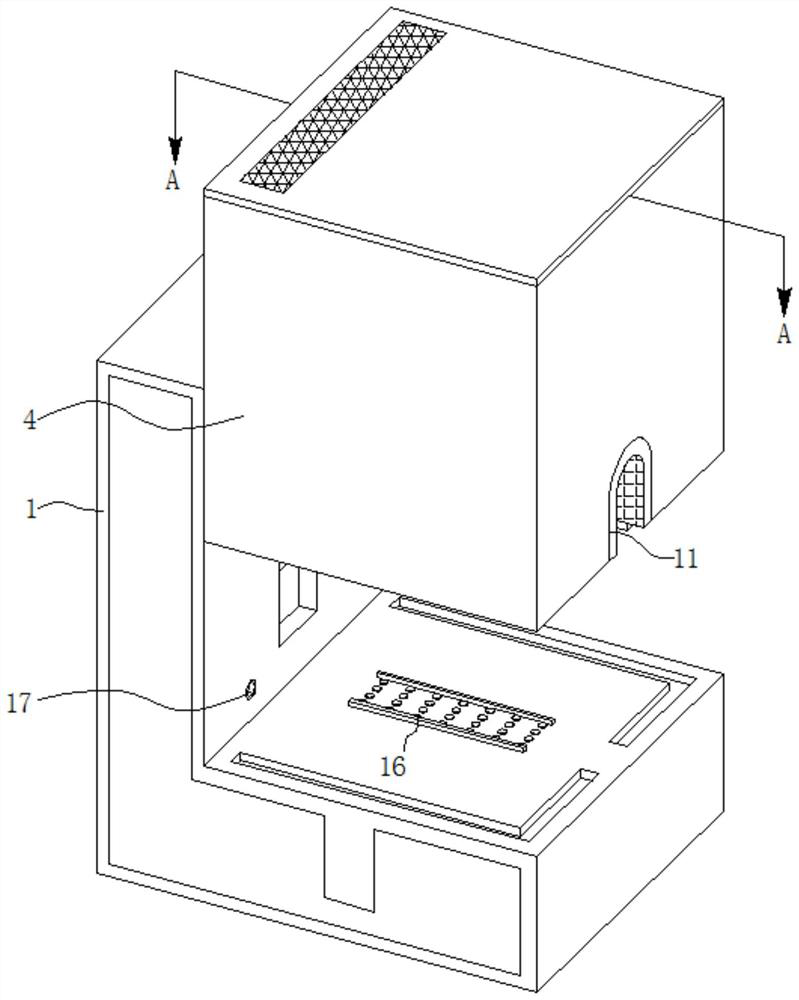
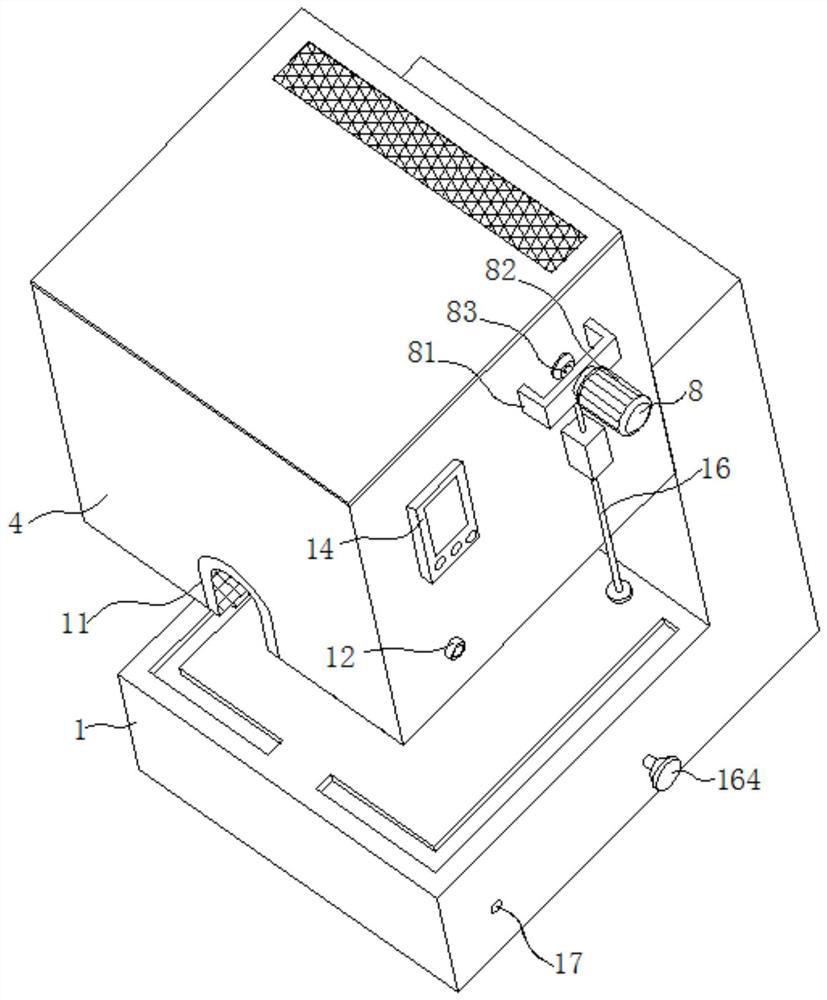
[0034] refer to Figure 1-4 , a physical therapy device for nursing and treating nerve injuries, comprising a bottom case 1, an electric telescopic rod 3, an upper case 4, a traditional Chinese medicine evaporation mechanism 7, an air supply mechanism 8, an air duct 9, and a perforated cover 10, wherein:
[0035] There is a first chamber 2 inside the bottom case 1, and the electric telescopic rod 3 is fixedly connected to the bottom of the first chamber 2. The electric telescopic rod 3 is used to adjust the height of the upper case 4 and control the cooperation between the upper case 4 and the bottom case 1. , the first chamber 2 is provided with a chute opening 15, the chute opening 15 makes the upper shell 4 move smoothly in the vertical direction, the upper shell 4 is slidably connected to the chute opening 15, and the telescopic end of the electric telescopic rod 3 Fixedly connected to the upper shell 4, the bottom shell 1 is matched with the upper shell 4, and the second ...
Embodiment 2
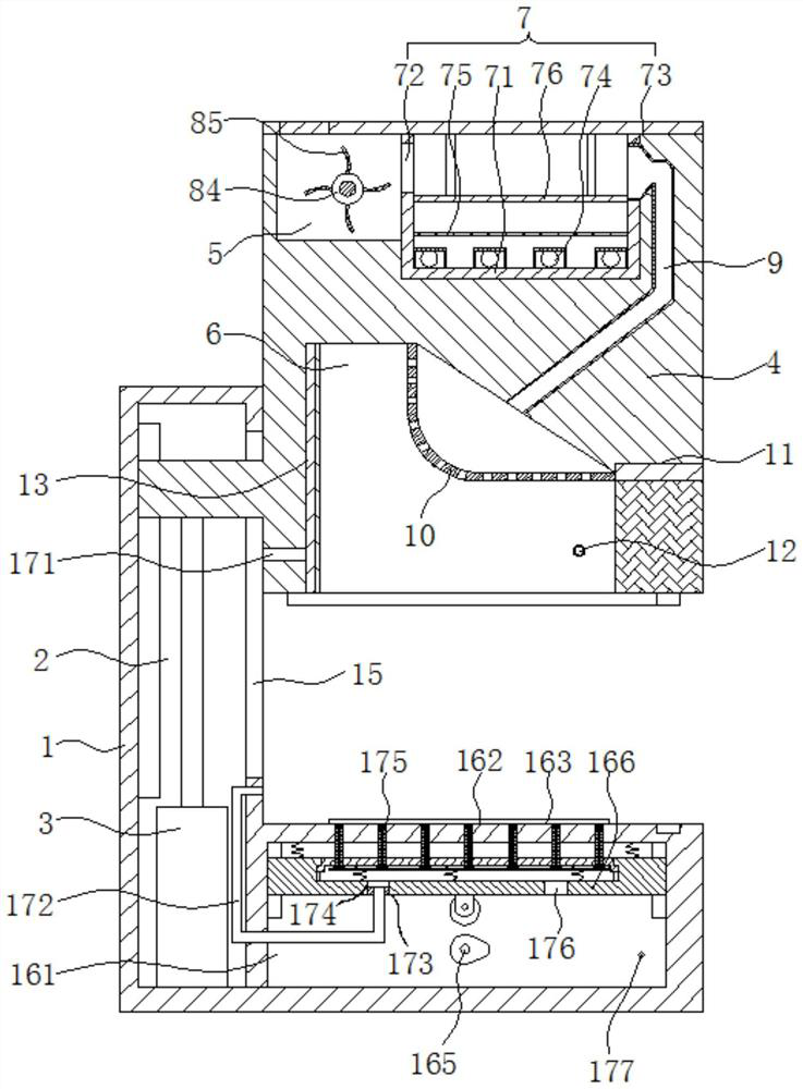
[0040] Because it takes a long time to use traditional Chinese medicine gas to treat the legs, placing the legs horizontally on the bottom shell 1 for a long time will easily lead to soreness and numbness of the calves, and the legs cannot be bent, so that the patient cannot be treated for a long time. Refer to Figure 1-8 , as another preferred embodiment of the present invention, on the basis of Embodiment 1, it also includes a massage mechanism 16 for avoiding leg paralysis. The massage mechanism 16 includes a third chamber 161, a first through hole 162, two parallel chambers The limit strip 163, the transmission mechanism 164, the push assembly 165 and the massage assembly 166, the inside of the bottom shell 1 opens a third chamber 161, the third chamber 161 is used to install the push assembly 165 and the massage assembly 166, the third chamber The upper end of 161 is provided with a number of first through holes 162, and two parallel limiting bars 163 are fixedly connecte...
Embodiment 3
[0049] When the first massaging part 1664 and the second massaging part 16663 are used to massage the legs, since the temperature of the first massaging part 1664 and the second massaging part 16663 is relatively low, it is uncomfortable to squeeze and massage the legs, refer to Figure 1-10 , as another preferred embodiment of the present invention, on the basis of Embodiment 2, it also includes a heating mechanism 17 for heating up the first massaging element 1664 and the second massaging element 16663, and the heating mechanism 17 includes a second through hole 171, Conduit 172, sealing sleeve 173, the third through hole 174, heat collecting assembly 175, the fifth through hole 176 and the second air outlet pipe 177, offer the second through hole 171 on the upper shell 4, the second through hole 171 is used for placing The hot gas in the chamber 6 is introduced into the conduit 172, the second through hole 171 communicates with the placement chamber 6, the bottom end of the ...
PUM
 Abstract
Description
Claims
Application Information
 - R&D
- Intellectual Property
- Life Sciences
- Materials
- Tech Scout
- Unparalleled Data Quality
- Higher Quality Content
- 60% Fewer Hallucinations
Browse by: Latest US Patents, China's latest patents, Technical Efficacy Thesaurus, Application Domain, Technology Topic, Popular Technical Reports.
© 2025 PatSnap. All rights reserved.Legal|Privacy policy|Modern Slavery Act Transparency Statement|Sitemap|About US| Contact US: help@patsnap.com