Sand box for copper furnace foundry casting

A sand box and foundry technology, which is applied to casting molding equipment, molding boxes, molding machines, etc., can solve the problems of reducing work efficiency, easy agglomeration, troublesome sand discharge, etc., so as to improve work efficiency, improve product qualification rate, The effect of guaranteeing the tight effect

Pending Publication Date: 2021-12-24
徐永上
View PDF1 Cites 3 Cited by
  • Summary
  • Abstract
  • Description
  • Claims
  • Application Information

AI Technical Summary

Problems solved by technology

It can solve the problem that the existing sand box for copper furnace foundry casting needs to compact the sand and gravel filled in the sand box when it is used, while the existing sand box for copper furnace sand foundry casting can ensure the sand and gravel compaction due to the lack of internal effect components, so there is a defect that the compacting effect cannot be ensured. At the same time, because the existing sand box for sand foundry in copper furnace needs to open the sand vent hole at the bottom of the sand box to release sand after use, the sand vent hole needs to be turned over The sand box can only be opened, which makes the sand discharge more troublesome
[0004] The above-mentioned patent still has the following problems in the specific use process: the movable plate and the cylinder are connected by the upper pneumatic telescopic rod and the lower pneumatic telescopic rod, which can solve the problem that the existing sand box for copper furnace sand casting needs to be filled when it is in use. However, in the process of compacting the sand and gravel, only the left and right sides can be compacted against each other, and it cannot be compacted from top to bottom; thus, the sand and gravel cannot be fully compacted. Practical operation will affect the quality of subsequent casting products. At the same time, sand and gravel heated by high-temperature copper water after pouring are prone to agglomeration, and in the subsequent secondary utilization process, manual crushing is still required multiple times, which is time-consuming and labor-intensive, reducing work efficiency

Method used


Image

  • Sand box for copper furnace foundry casting
  • Sand box for copper furnace foundry casting
  • Sand box for copper furnace foundry casting

Examples


Embodiment Construction

[0028] The following will clearly and completely describe the technical solutions in the embodiments of the present invention with reference to the accompanying drawings in the embodiments of the present invention. Obviously, the described embodiments are only some, not all, embodiments of the present invention. Based on the embodiments of the present invention, all other embodiments obtained by persons of ordinary skill in the art without making creative efforts belong to the protection scope of the present invention.

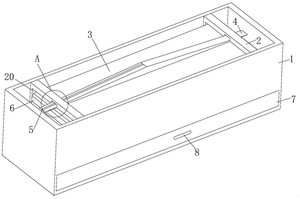
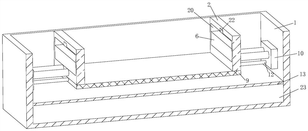
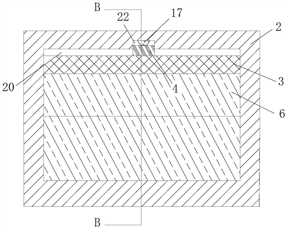
[0029] see Figure 1 to Figure 8 , the present invention provides a technical solution:

[0030]A sand box for copper furnace foundry, comprising a sand box main body 1, the inside of the sand box main body 1 near the lower end is fixedly connected with a filter screen 13 by screws, and the filter screen 13 is used to filter sand blocks produced after pouring, To prepare for the subsequent sand crushing work, and the inside of the sand box main body 1 is divi...


PUM


Abstract

The invention relates to the field of sand boxes, in particular to a sand box for copper furnace foundry casting. The sand box comprises a sand box body, wherein a filter screen is fixedly connected to the position, close to the lower end, in the sand box body through screws, the interior of the sand box body is divided into two parts by the filter screen, the part above the filter screen serves as a sand cavity, and the part below the filter screen serves as a collecting cavity; an opening is formed in the position, close to the bottom of the outer surface of the front end of the sand box body, below the filter screen, a collecting box is arranged in the opening, the collecting box is movably connected into the collecting cavity through the opening and is sealed with the periphery of the opening, and a grip is fixedly connected to the middle of the front end of the outer surface of the collecting box; and a bottom plate is arranged above the filter screen, and rotating shafts are fixedly connected to the left side and the right side of the bottom plate. According to the structure of the device, compaction of the left side and the right side of sand before casting can be achieved, and compaction can be conducted from top to bottom; automatic sand discharging can be conducted when movable plates reset, so that the recovery efficiency is greatly improved; and after casting is completed, caked sand can be smashed, so that the sand recovery benefit is improved.

Description

technical field [0001] The invention relates to the field of sand boxes, in particular to a sand box for copper furnace foundry casting. Background technique [0002] Foundry casting refers to the use of clay-bonded sand as the molding material to produce castings. When foundry casting, a sand box is needed. First, the lower half of the mold is placed on the flat plate, and the sand box is filled with sand and gravel. Turn the finished sand mold over 180 degrees, put the upper half mold, sprinkle the parting agent, put it on the sand box, fill it with sand and gravel, tighten it, and scrape it flat, turn the upper sand box 180 degrees, take out the upper and lower half molds respectively, Then turn the upper mold 180 degrees and close it with the lower mold. The sand mold is finished and waits for pouring. Therefore, the sand box is an indispensable tool in the foundry casting process; [0003] Existing patent (notification number: CN112719232A) a sand box for copper furna...

Claims


Application Information

Patent Timeline
Patent Type & Authority Applications(China)
IPC IPC(8): B22C21/00B22C5/06B22C5/14B22C15/02
CPCB22C21/00B22C5/06B22C5/14B22C15/02
Inventor 徐永上全彩勤
Owner 徐永上
Why Eureka
Try Eureka