
Shielding door structure

A technology for shielding doors and door frames, applied in the field of door structures, can solve problems such as inconvenience and inability to shield signals, and achieve the effects of achieving continuity, solving inconvenient access, saving costs and handling efficiency.

Pending Publication Date: 2021-12-24
丹东市瑞德磁电子有限公司
View PDF0 Cites 0 Cited by
  • Summary
  • Abstract
  • Description
  • Claims
  • Application Information

AI Technical Summary

Problems solved by technology

[0003] The main purpose of the present invention is to overcome the deficiencies in the above-mentioned technologies, and provide a shielded door structure to solve the technical problems of the inconvenience of medical equipment entering the shielded room and the unshielded signal in the prior art

Method used


Image

  • Shielding door structure
  • Shielding door structure
  • Shielding door structure

Examples


Embodiment 1

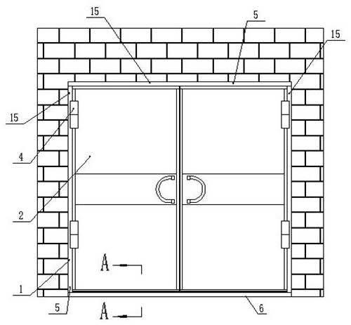
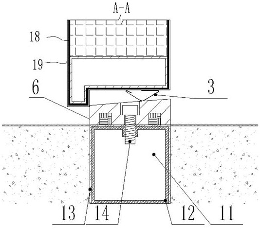
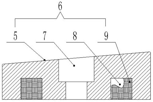
[0031] by Figure 1-7 It can be seen that this embodiment discloses a shielded door structure. A doorframe 1 is arranged on the wall of the shielded room. The doorframe 1 includes doorframes provided with slopes 5 on the left, right and upper doorframes of the doorframe 1. Bar 15 is arranged on the ground and the left and right ends are respectively connected with the left and right door frame bars 15 and the door sill body 6 with inclined plane 5 is arranged. After the door frame bar 15 and the door sill body 6 are assembled into the door frame body 1, the door frame bar 15 The orientation of the inclined plane 5 and the inclined plane 5 of the door sill body 6 are consistent, such as Image 6 , Figure 7 shown.

[0032] The two screen doors 2 are respectively hinged on the door frame body 1 through hinge shafts 4 .

[0033] Depend on Figure 7 , Figure 9 It can be seen that the door frame bar 15 is arranged on the door frame body 1 in this way, the inner edge of the do...

Embodiment 2

[0051] Depend on Figure 8 It can be seen that this embodiment discloses a shielded door structure. The door frame 1 is arranged on the wall of the shielded room, and the shielded door 2 is a single-sided door opening structure. The left shielded door 2 in Embodiment 1 is selected, and the left shielded door Door reeds 3 are respectively arranged on the four contour surfaces of the screen door 2, such as Figure 4 shown. The door reeds 3 are respectively arranged on the four contour surfaces to fit and connect with the door frame body 1, and the door reeds 3 are squeezed and compressed by the slope 5 of the door frame body 1 respectively, thereby realizing airtight connection. Other uniform structures are the same in the embodiments, so , to isolate the electrical signal outside the shielded room, so that the electrical signal cannot enter the shielded room, and ensure the purity of the electromagnetic field in the shielded room, so that it is not interfered by external elect...


PUM


Abstract

The invention discloses a shielding door structure. The shielding door structure is mainly characterized in that one end of a door hinge shaft is connected with a door frame body; the other end of the door hinge shaft is connected with a shielding door; when the shielding door is closed, the door hinge shaft serves as a hinge point, a door reed on the outline face of the shielding door is compressed on the door frame body, and the shielding door is connected with the door frame body in an attached mode; the door frame body comprises door frame strips and a doorsill whole body; the door frame strips are arranged on left, right and upper door frames of the door frame body and are provided with inclined planes; the doorsill whole body is arranged on the ground and is provided with inclined planes; and the left and right ends of the doorsill whole body are connected with the left and right door frame strips respectively. Conductive continuity of the shielding door is achieved, and the situation that, for an electromagnetic field generated by special equipment in a blocking and refraction space in a shielding room, the electromagnetic field in the shielding room is not exposed to the outside is guaranteed; and electric signals outside the shielding room are isolated, so that electromagnetic signals cannot enter the shielding room and the shielding room is not interfered by external electromagnetic signals. The problem that entering and exiting of large-scale magnetic field equipment are inconvenient is solved by dismounting the doorsill whole body on the ground, so that the transportation and carrying cost is reduced, and the carrying efficiency is improved.

Description

technical field [0001] The invention relates to the technical field of door structures, in particular to a screen door structure. Background technique [0002] At the beginning of the construction of the shielding room of the existing medical equipment manufacturer, problems such as equipment replacement and signal shielding were not considered. The threshold was designed to be fixed, which caused inconvenience to equipment access and equipment replacement and maintenance. However, some medical equipment manufacturers’ shielded rooms forcibly removed the threshold, which resulted in no close fit between the door reed and the door frame, and lost the continuity of conductivity, resulting in the electromagnetic field in the shielded room being interfered by external signals, and the shielding effect was poor. . Contents of the invention [0003] The main purpose of the present invention is to overcome the deficiencies in the above-mentioned technologies and provide a shield...

Claims


Application Information

Patent Timeline
IPC IPC(8): E06B5/18E06B3/36E06B1/52E06B1/70E06B7/22E06B3/70
CPCE06B5/18E06B3/362E06B1/526E06B1/70E06B7/22E06B3/7001E06B2001/707
Inventor 崔月驰林乐兴
Owner 丹东市瑞德磁电子有限公司
Learn More