
Lubricating oil tank for textile machine

A technology of lubricating oil and textile, applied in the direction of lubricating oil container, engine lubrication, lubricating parts, etc., can solve the problems of inconvenient and quick disassembly, blockage of oil pipe, and inconvenient storage of oil discharge pipe inside the oil tank, so as to achieve the effect of convenient disassembly.

Inactive Publication Date: 2021-12-24
XIANGSHUI ZHONGXING TEXTILE CO LTD
View PDF0 Cites 0 Cited by
  • Summary
  • Abstract
  • Description
  • Claims
  • Application Information

AI Technical Summary

Problems solved by technology

[0003] However, the lubricating oil tanks used in traditional textiles are mostly fixed by nuts, and it is not convenient to quickly disassemble them when they need to be replaced and repaired. The oil tank is usually not equipped with a structure for filtering the velvet, which is easy for the lint to enter the oil tank, causing oil pipes Blockage, when some lubricating oil is reinjected into the fuel tank, sediment will often be formed. If the sediment is not cleaned up, the ash will affect the oil delivery. When the oil drain pipe is not in use, it is not convenient to put it into the oil tank body, and it is easy to cause pollution to the oil drain pipe.

Method used


Image

  • Lubricating oil tank for textile machine
  • Lubricating oil tank for textile machine
  • Lubricating oil tank for textile machine

Examples


Embodiment Construction

[0025] In order to make the technical means, creative features, goals and effects achieved by the present invention easy to understand, the present invention will be further described below in conjunction with specific embodiments.

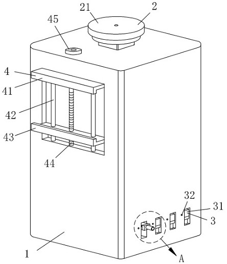
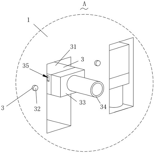
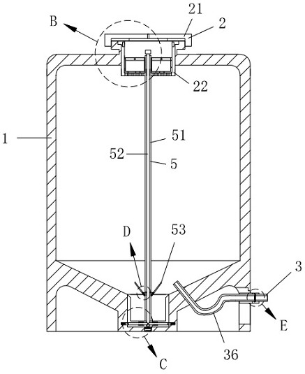
[0026] Such as Figure 1-Figure 9 As shown, a lubricating oil tank for textile machines according to the present invention includes a box body 1, and one end of the box body 1 is connected with a fixing structure 4 for fast fixing and dismounting of the box body 1, and the top end of the box body 1 It is connected with a filter structure 2 for preventing the velvet from entering the box body 1, a cleaning structure 5 for cleaning sediment is installed at the inner bottom of the box body 1, and a filter for oil discharge is installed at one end of the box body 1. Oil discharge structure 3.

[0027] Specifically, the fixed structure 4 includes a fixed plate 41, one end of the box body 1 is fixedly connected with the fixed plate 41, and one end of t...


PUM


Abstract

The invention relates to the technical field of textile, in particular to a lubricating oil tank for a textile machine. The lubricating oil tank comprises a tank body, one end of the tank body is connected with a fixing structure for quickly fixing and detaching the tank body, the top end of the tank body is connected with a filtering structure for preventing yarn wool from entering the tank body, a cleaning structure for cleaning sediments is mounted at the bottom end of the interior of the tank body, and an oil discharging structure for discharging oil is mounted at one end of the tank body. The tank body can be conveniently and rapidly installed and fixed to the textile machine through the fixing structure and can be conveniently disassembled, yarn velvet in air can be filtered through the filtering structure, the yarn velvet is prevented from entering the tank body along with lubricating oil, the oil discharging structure is prevented from being blocked, sediments in the lubricating oil can be collected and taken out in a centralized mode through the cleaning structure, the sediments are prevented from entering the oil discharging structure, and discharging of the lubricating oil in the tank body is conveniently controlled through the oil discharging structure.

Description

technical field [0001] The invention relates to the technical field of textiles, in particular to a lubricating oil tank for textile machines. Background technique [0002] The original meaning of textile is taken from the general term of spinning and weaving, but with the continuous development and improvement of the textile knowledge system and subject system, especially after the emergence of non-woven textile materials and three-dimensional composite weaving technologies, the current textile is not only a traditional Hand spinning and weaving also include non-woven fabric technology, modern three-dimensional weaving technology, modern electrostatic nano-netting technology and other textiles for clothing, industry and decoration. Weaving machines are needed in the re-weaving process. The machine needs to be lubricated with lubricating oil when it is working, so as to ensure the normal operation of the machine. In order to facilitate the addition of lubricating oil, a lubr...

Claims


Application Information

Patent Timeline
Patent Type & Authority Applications(China)
IPC IPC(8): F16N19/00F16N31/00F16N39/06B01D29/01B01D29/96B01D35/02B01D46/00B01D46/10
CPCF16N19/00F16N31/00F16N39/06B01D35/02B01D29/01B01D29/96B01D46/10F16N2039/007
Inventor 郑彩红袁以权袁宗兴崔丽红袁以东
Owner XIANGSHUI ZHONGXING TEXTILE CO LTD
Learn More