Spraying thermal heating production system

A production system and heating system technology, applied in waste heat treatment, lighting and heating equipment, furnace components, etc., can solve problems such as large temperature fluctuations, increased loss rate, excessive heat generation areas, etc., achieve stable temperature fluctuations, increase transportation Speed, the effect of increasing the length of the furnace body

Pending Publication Date: 2021-12-28
广西福煌实业有限公司
View PDF0 Cites 0 Cited by
  • Summary
  • Abstract
  • Description
  • Claims
  • Application Information

AI Technical Summary

Problems solved by technology

[0010] 1. Because the existing structure is a single-line production, only one process can be executed each time, and the finished enamel products need to repeat the sintering process in the kiln for many times, resulting in many cycles and low production efficiency;
[0011] 2. During the sintering process, the heat energy brought out by the product cannot be fully utilized, resulting in waste of heat energy;
[0012] 3. If it is necessary to realize the production of all technological processes, the total space occupied by various equipment is large, and the existing products need to be circulated, resulting in unnecessary space occupation;
[0013] 4. The sintering furnace and drying furnace of the existing enamel kiln are independent units, resulting in too many heating areas, so that the power of the equipment is large, the full load is 900KW, and the heat energy is not fully utilized;
[0014] 5. The vault structure and equipment structure are complicated, which makes maintenance and production equipment inconvenient;
[0015] 6. During the sintering process, the temperature fluctuates greatly, and the temperature cannot be kept constant, resulting in unstable product quality;
[0016] 7. When products go on and off the production line, manual circulation is required, which is inconvenient for product circulation and increases the loss rate during circulation;
[0017] 8. It is impossible to realize the assembly line production of finished products, which requires more personnel to operate the production

Method used


Image

  • Spraying thermal heating production system
  • Spraying thermal heating production system
  • Spraying thermal heating production system

Examples


Embodiment Construction

[0043] The following will clearly and completely describe the technical solutions in the embodiments of the present invention with reference to the accompanying drawings in the embodiments of the present invention. Obviously, the described embodiments are only some, not all, embodiments of the present invention. Based on the embodiments of the present invention, all other embodiments obtained by persons of ordinary skill in the art without making creative efforts belong to the protection scope of the present invention.

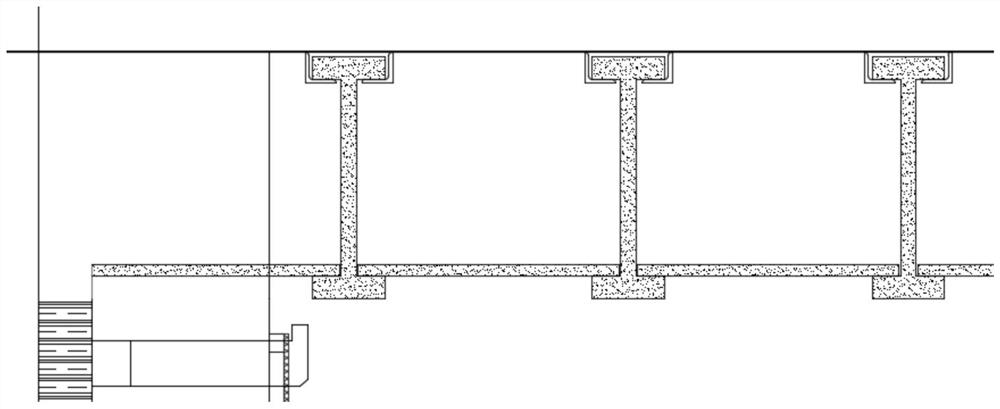
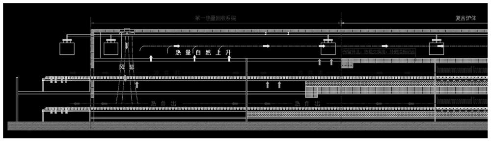
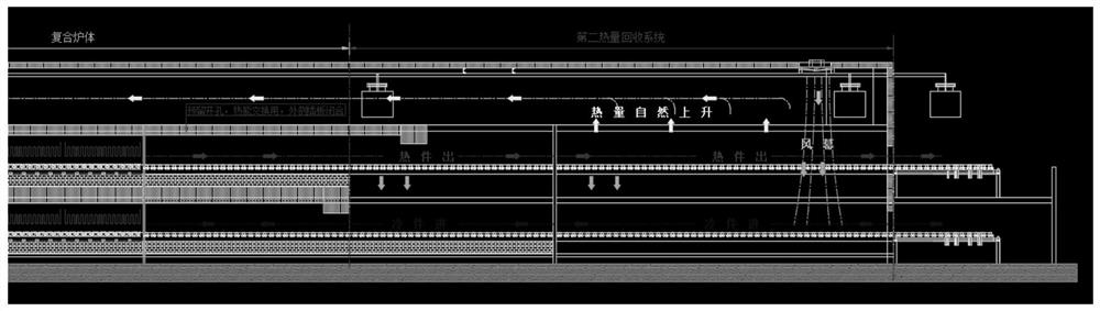
[0044] see Figure 1-8, a thermal heating production system for spraying, including a production system, a compound furnace body, a heat recovery system, a compound conveying system and a heating system. The production system is divided into A work area and B work area, and both A work area and B work area include Roller conveying line, belt conveying line, hanging conveying line, heat recovery system, sintering furnace, drying furnace, blank conveying line, g...


PUM


Abstract

The invention relates to the technical field of heating production systems, and discloses a spraying thermal heating production system which comprises a production system, a composite furnace body, a heat energy recovery system, a composite conveying system and a heating system. The production system is divided into a working area A and a working area B; each of the working area A and the working area B comprises a roller way conveying line, a belt conveying line, a hanging conveying line, a heat energy recovery system, a sintering furnace, a drying furnace, a blank conveying line, a glaze spraying area and a receiving area; and the working area A and the working area B form a composite thermal heating production system. The spraying thermal heating production system has the advantages of being high in production efficiency, capable of avoiding heat energy waste, small in occupied area and convenient to maintain.

Description

technical field [0001] The invention relates to the technical field of heating production systems, in particular to a spraying thermal heating production system. Background technique [0002] Surface treatment sintering heat heating equipment is an indispensable main equipment in the production of enamel products. Its heating structure and heat energy utilization technology greatly affect the output, quality and cost of products. [0003] The basic structure and principle of the existing sintering heating equipment: [0004] Existing sintering heating equipment uses steel frames as supporting structures; walls and vaults are built with refractory materials to form vaulted tunnel sintering kilns; heating elements are installed on four sides of the middle part of the kiln chamber; Wrap and fill the insulation material; assemble the fixed shell steel plates on the outer sides and top of the insulation material to form the main body of the sintering kiln. [0005] In front of ...

Claims


Application Information

Patent Timeline
Patent Type & Authority Applications(China)
IPC IPC(8): C23D9/00C23D9/10F27D17/00
CPCC23D9/00C23D9/10F27D17/004Y02P10/25
Inventor 庞耀勇吴润楷
Owner 广西福煌实业有限公司
Why Eureka
Try Eureka