Full-automatic electronic lock body

An electronic lock, fully automatic technology, applied to non-mechanical transmission-operated locks, building locks, buildings, etc., to achieve the effect of improving work efficiency and facilitating recycling work

Inactive Publication Date: 2021-12-28
浙江守护者智能家居服务有限公司
View PDF5 Cites 0 Cited by
  • Summary
  • Abstract
  • Description
  • Claims
  • Application Information

AI Technical Summary

Problems solved by technology

[0005] In view of the problems existing in the prior art, the purpose of the present invention is to provide a fully automatic electronic lock body, which can realize that the main tongue is stuck in the tongue groove due to the oxidation and corrosion of the air during the long-term use of the fully automatic electronic lock body. When the lock cannot be closed, because the motor in the electronic lock body continues to work, the temperature inside the electronic lock body gradually rises, causing the expansion balloon to expand due to heat, and the limit block gradually floats on the buoyancy of the lubricating fluid, so that the lubricating fluid flows from The channel begins to penetrate, and then the infiltrated lubricating fluid lubricates the main tongue, so that the main tongue can be retracted into the tongue groove to complete closure, and then the lubricating fluid falls from the surface of the main tongue into the storage base, forming a secondary lubricating fluid that is absorbed by the adsorption balloon , while the electronic lock body is stuck and cannot be closed when the temperature gradually rises, the deformation balloon squeezes the secondary lubricating fluid, sprays the secondary lubricating fluid from the liquid outlet, and lubricates the lower end of the main tongue to a certain extent , so as to facilitate the recovery of the main tongue and improve the efficiency of lubrication

Method used


Image

  • Full-automatic electronic lock body
  • Full-automatic electronic lock body
  • Full-automatic electronic lock body

Examples


Embodiment

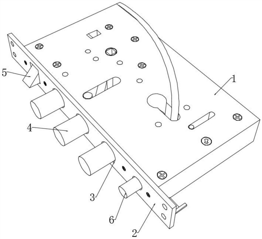
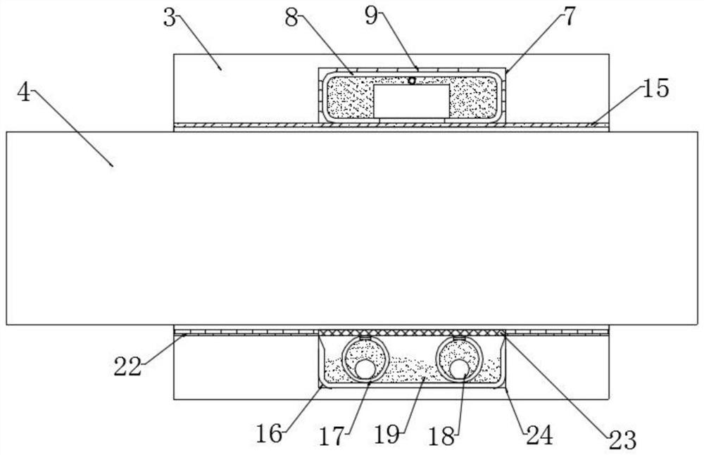
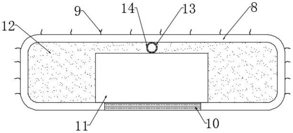
[0041] see Figure 1-5 , a fully automatic electronic lock body, including an electronic lock block 1, the outer end of the electronic lock block 1 is fixedly connected with a guide plate 2, and the outer end of the guide plate 2 is dug with a plurality of evenly distributed tongue grooves 3, and the tongue groove 3 is slidingly connected with a main The tongue 4 is slidingly connected with the oblique tongue 5 inside the guide plate 2, and the safety tongue 6 is slidably connected with the inside of the guide plate 2. The groove 7 and the second groove 24, the second groove 24 is provided with an adsorption device, the first groove 7 is provided with an expansion balloon 8, and the expansion balloon 8 is fixedly connected with the inner wall of the first groove 7 A plurality of evenly distributed heat-conducting fibers 9, a flow channel 10 is embedded at the lower end of the inflatable balloon 8, and a limit block 11 is provided at the inner bottom of the inflatable balloon 8...


PUM


Abstract

The invention discloses a full-automatic electronic lock body, and belongs to the field of electronic lock bodies, and the scheme can realize that in the long-time use process of the full-automatic electronic lock body, when a main tongue is clamped in a tongue groove due to oxidation corrosion of air and cannot be closed, a motor in the electronic lock body still continues to work, the temperature inside the electronic lock body is gradually increased, an expansion balloon is heated to expand, a limiting block gradually floats under the buoyancy action of lubricating liquid, the lubricating liquid begins to permeate from a flowing channel, then the permeated lubricating liquid lubricates the main tongue, then the lubricating liquid falls into a storage base from the surface of the main tongue, and formed secondary lubricating liquid is absorbed by an adsorption balloon, and when the electronic lock body is clamped and cannot be closed, and the temperature is gradually increased, a deformation balloon extrudes the secondary lubricating liquid, the secondary lubricating liquid is sprayed out from a liquid outlet, the lower end of the main tongue is lubricated to a certain extent, so that the main tongue is conveniently recycled, and the working efficiency of lubrication is improved.

Description

technical field [0001] The invention relates to the field of electronic lock bodies, more specifically, to a fully automatic electronic lock body. Background technique [0002] The lock body is one of the components of the lock. There are many kinds of lock bodies. The common ones are one-way lock body, three-way lock body, four-way lock body, etc. They are generally used on anti-theft doors and are responsible for the basic anti-theft work of anti-theft doors. The lock cylinder controls the operation of the lock body, and the lock body is responsible for opening and locking the doors and windows, and plays an important role in anti-theft. [0003] At present, during the use of the lock body, a fully automatic electronic lock body has begun to exist, and during the use of the fully automatic electronic lock body, there may be oxidation and corrosion of the main tongue due to the use of the generated, resulting in a gap in the tongue groove. It is stuck or recovered slowly, ...

Claims


Application Information

Patent Timeline
IPC IPC(8): E05B47/00E05B17/08E05B15/16
CPCE05B47/0001E05B17/08E05B15/16
Inventor 梅积静尤锦浪陈骄奇
Owner 浙江守护者智能家居服务有限公司
Why Eureka
Try Eureka